Method and system for eliminating direct-current deviation of ultrasonic echo signal

A technology of DC deviation and signal elimination, which is used in the generation of ultrasonic/sonic/infrasonic waves, the detection of response signals, and the use of sonic/ultrasonic/infrasonic waves for material analysis, etc. problems, to achieve the effect of prolonging the service life, enhancing the signal-to-noise ratio, and eliminating the cumulative effect

Inactive Publication Date: 2020-06-09
奈第电子科技(上海)有限公司
View PDF11 Cites 2 Cited by
  • Summary
  • Abstract
  • Description
  • Claims
  • Application Information

AI Technical Summary

Problems solved by technology

[0003] Existing ultrasonic industrial detection detection and transmission circuits usually require a large dynamic range, and may work in the receiving and amplifying channel in the amplification range of about -40db to +80db. In such a wide range of adjustments, the DC Deviation elimination often adopts the method of capacitor DC blocking at the last stage, but this mode still cannot eliminate the DC deviation of ADC, and because of the existence of DC blocking capacitors, the transmitted pulse energy is blocked, so the weak echo signal in front will be caused by If the blockage time is too long, the detection near the surface cannot be implemented. There are also DC coupling amplification modes, and digital dynamic adjustment of the DC bias of the front stage, but this requires more complex control circuits, and the ability to suppress temperature drift is also affected. limit

Method used


Image

  • Method and system for eliminating direct-current deviation of ultrasonic echo signal
  • Method and system for eliminating direct-current deviation of ultrasonic echo signal

Examples


Embodiment Construction

[0026] The specific implementation manners of the present invention will be further described below in conjunction with the drawings and examples. The following examples are only used to illustrate the technical solution of the present invention more clearly, but not to limit the protection scope of the present invention.

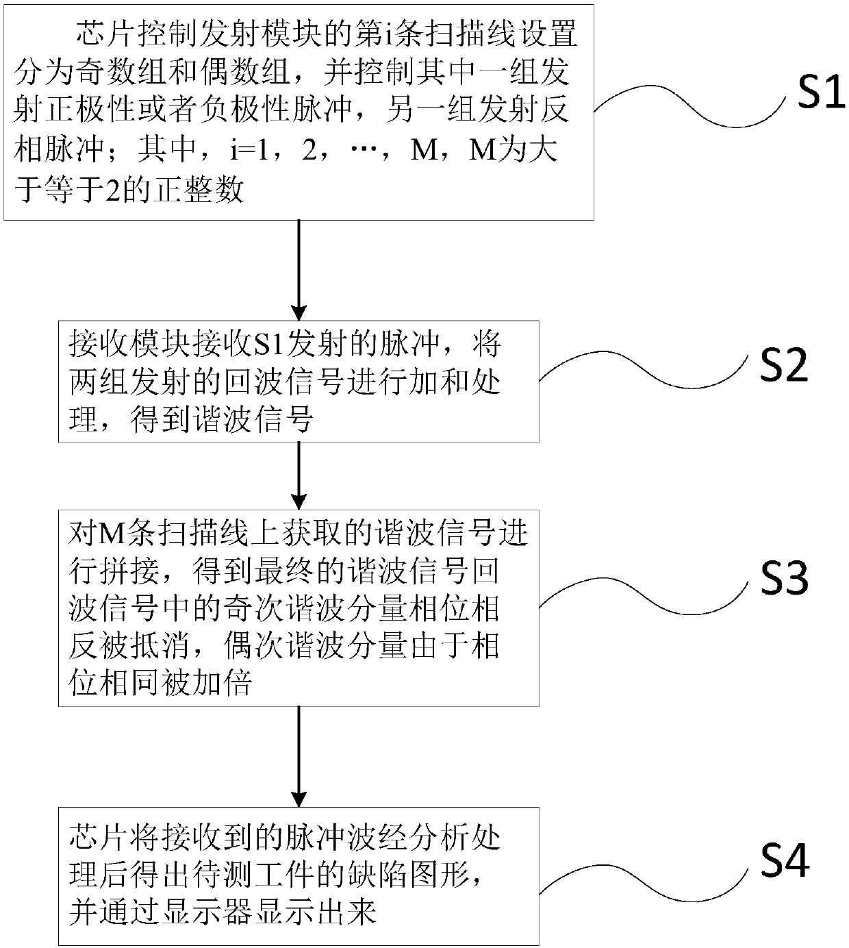
[0027] Such as figure 1 As shown, the present invention is a method for eliminating DC deviation of an ultrasonic echo signal, comprising the following steps:

[0028] S1, the chip controls the emission module to divide the emission of the i-th scanning line into odd groups and even groups, and control one group of emission lines to emit positive or negative polarity pulses, and the other group of emission lines to emit anti-phase pulses, where , i=1, 2, ..., M, M is a positive integer greater than or equal to 2;

[0029] S2, the receiving module receives the pulse transmitted by S1, and adds and processes the echo signals transmitted by the two groups to...


PUM


Abstract

The invention discloses a method for eliminating direct-current deviation of an ultrasonic echo signal. The method comprises steps that S1, a chip controls a transmitting module to divide the transmitted ith scanning line into an odd number group and an even number group, one group of transmitting lines is controlled to transmit positive polarity or negative polarity pulses, the other group of transmitting lines is controlled to transmit reverse phase pulses, i = 1, 2,..., M, and M is a positive integer larger than or equal to 2; S2, a receiving module receives the pulses transmitted in the step S1, and the two groups of transmitted echo signals are summed to obtain harmonic signals; S3, the harmonic signals obtained on the M scanning lines are spliced to obtain a final harmonic signal; and S4, the received pulse waves are analyzed and processed by the chip to obtain a defect graph of the to-be-detected workpiece, and the defect graph is displayed through a display. The method is advantaged in that purposes of eliminating direct-current deviation and enhancing the signal-to-noise ratio are both achieved, and complexity of ultrasonic echo signal processing is lowered.

Description

technical field [0001] The invention relates to the field of ultrasonic detection, in particular to a method and system for eliminating DC deviation of ultrasonic echo signals. Background technique [0002] Ultrasonic testing is a detection method for testing internal defects of materials by using the difference in acoustic properties of materials and their defects to the energy changes in the reflection of ultrasonic wave propagation and penetration time. [0003] Existing ultrasonic industrial detection detection and transmission circuits usually require a large dynamic range, and may work in the receiving and amplifying channel in the amplification range of about -40db to +80db. In such a wide range of adjustments, the DC Deviation elimination often adopts the method of capacitor DC blocking at the last stage, but this mode still cannot eliminate the DC deviation of ADC, and because of the existence of DC blocking capacitors, the transmitted pulse energy is blocked, so th...

Claims


Application Information

Patent Timeline
Patent Type & Authority Applications(China)
IPC IPC(8): G01N29/46G01N29/44G01N29/34G01N29/36
CPCG01N29/46G01N29/449G01N29/343G01N29/36G01N2291/0289
Inventor 庄景文
Owner 奈第电子科技(上海)有限公司
Why Eureka
Try Eureka