A light control light switch

An optical switch and light source technology, applied in the field of optical control, can solve the problems of narrow modulation wavelength range, strong control of light intensity, etc., and achieve the effects of fast modulation speed, high modulation efficiency, and fast acceleration

Active Publication Date: 2022-05-20
GUIZHOU MINZU UNIV
View PDF0 Cites 0 Cited by
  • Summary
  • Abstract
  • Description
  • Claims
  • Application Information

AI Technical Summary

Problems solved by technology

This method has a very high modulation speed, but requires a strong control of light intensity, and can only work near a specific wavelength, and the modulation wavelength range is narrow

Method used


Image

  • A light control light switch

Examples


Embodiment 1

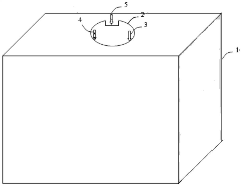
[0028] Such as figure 1 As shown, in this embodiment, an optically controlled optical switch includes a magnetic base 1 , a graphene sheet 2 with a gap and a driving light source, and the gap runs through the upper and lower surfaces of the graphene sheet 2 . The graphene sheet 2 is suspended on the magnetic base 1 under the action of a magnetic field, and the graphene sheet 2 is provided with a driving light source for driving the graphene sheet 2 to move in a circular direction. The driving light source includes a first control light input terminal 3 and a second control light input terminal 4, and the first control light input terminal 3 and the second control light input terminal 4 are distributed on both sides of the notch.

[0029] The magnetic base 1 is a RuFeB block material with a smooth surface, the diameter of the graphene sheet 2 is 20 microns, the gap is 2 microns wide and 1 micron deep, the first control light input terminal 3 and the second control light input t...


PUM

PropertyMeasurementUnit
angle of incidenceaaaaaaaaaa
diameteraaaaaaaaaa

Abstract

The invention discloses an optically controlled optical switch, which comprises a magnetic base, a graphene sheet with a gap and a driving light source, the graphene sheet is suspended on the magnetic base under the action of a magnetic field, and the graphene sheet is provided with a A driving light source for driving the circular motion of the graphene sheet. The beneficial effect of the present invention is: by controlling light irradiation, changing the magnetic polarization direction deflection of the graphene sheet, thereby rotating under the action of the magnetic field, so that the regulated light passes through or does not pass through the gap, so as to realize the modulation of the regulated light. The light-controlled optical switch can realize simultaneous modulation in the range of ultraviolet to infrared spectrum, and the modulation speed is fast and the modulation efficiency is high.

Description

technical field [0001] The invention relates to the technical field of light control, in particular to a light control light switch. Background technique [0002] High-speed optically controlled optical switches have a wide range of applications in optical integrated circuits, optical computing, all-optical circuits, and optical interconnections. Traditional light-controlled optical switches mainly use the nonlinear effect of optical materials, that is, use control light with strong light intensity to change the refractive index of optical materials, thereby adjusting the transmittance or reflectance of the controlled light, thereby realizing the control of light to light. . This method has a very high modulation speed, but requires a strong control of light intensity, and can only work near a specific wavelength, and the modulation wavelength range is narrow. Contents of the invention [0003] The technical problem to be solved by the present invention is to provide a l...

Claims


Application Information

Patent Timeline
Patent Type & Authority Patents(China)
IPC IPC(8): G02B26/02
CPCG02B26/02
Inventor 刘江涛李伟民罗胜耘李林福马彦兵吴雷
Owner GUIZHOU MINZU UNIV
Why Eureka
Try Eureka