
Angular point detection method based on visible light and infrared universal calibration board

A technology of corner point detection and calibration board, which is applied in image data processing, instrumentation, computing, etc., can solve the problems of feature point extraction, corner point blurring, poor image contrast, etc., and achieve good image contrast, accurate calibration results, and corner point detection. Imaging clear effect

Inactive Publication Date: 2020-06-09
DALIAN UNIV OF TECH
View PDF0 Cites 5 Cited by
  • Summary
  • Abstract
  • Description
  • Claims
  • Application Information

AI Technical Summary

Problems solved by technology

Due to the different sensing spectra of visible light cameras and infrared cameras, the black and white checkerboard calibration plate or ordinary circular array calibration plate cannot clearly image under the infrared camera, that is, the black and white checkerboard calibration plate cannot be used to calibrate the infrared camera
[0003] At present, the common infrared camera calibration boards are imaged by heating or cooling to create temperature differences. This kind of calibration board usually has the disadvantages of blurred corners, poor image contrast, and high production costs.
Not only that, when shooting the existing checkerboard calibration board, the checkerboard calibration board cannot cover the entire camera field of view, that is, the current corner detection algorithm can only detect the complete checkerboard image, so the checkerboard cannot be used Extract the feature points of the edge area, so the calibrated internal and external parameters of the camera must be inaccurate

Method used


Image

  • Angular point detection method based on visible light and infrared universal calibration board
  • Angular point detection method based on visible light and infrared universal calibration board
  • Angular point detection method based on visible light and infrared universal calibration board

Examples


Embodiment Construction

[0028] The present invention will be further described in detail below with reference to the accompanying drawings and specific embodiments.

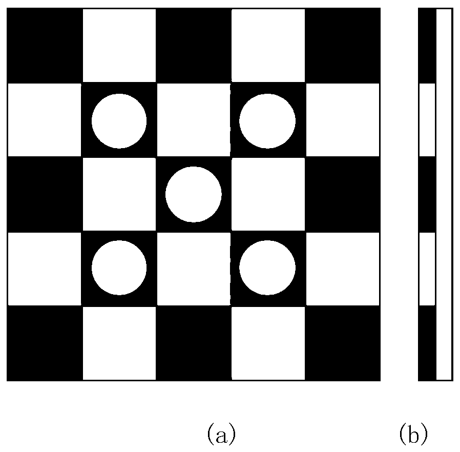
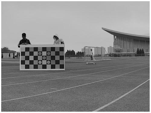
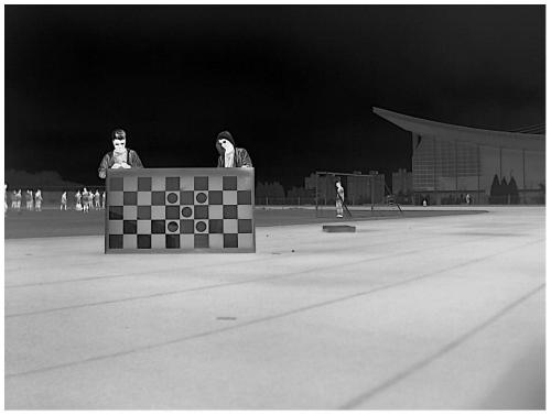
[0029] The invention proposes a calibration board that is common to visible light and infrared cameras. The calibration board is composed of a calibration board bottom plate and two rectangular sheets of different materials. The calibration board is provided with one or several pieces of certain colors or shapes. The purpose of the logo is to determine the world coordinate system of the checkerboard pattern through the logo. The use of two materials to absorb photons in the visible light and infrared spectrum differently ensures that the calibration board can present a clear checkerboard pattern under both the visible light camera and the infrared camera. The following are specific cases:

[0030] The infrared camera has a spectral range of 8 to 14 μm, the highly polished aluminum flakes are in the full spectral range, the emissivity i...


PUM


Abstract

The invention discloses an angular point detection method based on a visible light and infrared universal calibration plate. The calibration plate is composed of a calibration plate bottom plate and two rectangular sheets made of different materials. The two sheets made of different materials comprise metal sheets and non-metal sheets, and the adjacent rectangular sheets are made of different materials; the two materials have different absorption degrees on visible light and infrared spectrum photons, so that the calibration plate is enabled to be clear in imaging under a visible light cameraand an infrared camera; an identifier is arranged on a checkerboard to mark the position of an initial unit grid, world coordinates of corners on a calibration board are determined, sub-pixel-level corner coordinates of four points of the initial unit grid are detected on a shot checkerboard image, and then the sub-pixel-level corner coordinates are diverged outwards through a homography matrix tofinally complete corner detection. The calibration plate is combined with an angular point detection method, so that the detection effect is more accurate and reliable.

Description

technical field [0001] The invention belongs to the technical field of camera calibration, and in particular relates to a corner point detection method based on a visible light and infrared universal calibration plate. Background technique [0002] Today, the combined use of visible light and infrared cameras has been widely used in military reconnaissance, autonomous driving, wildlife protection and other fields. The fusion of the image information captured by the visible light camera and the infrared camera can achieve complementary advantages and expand the use scenarios of the vision system. However, both visible light and infrared cameras need to be calibrated before use to obtain the corresponding internal and external parameters. Due to the difference in the sensing spectrum of the visible light camera and the infrared camera, the black and white checkerboard calibration board or the ordinary circular array calibration board cannot be clearly imaged under the infrare...

Claims


Application Information

Patent Timeline
Patent Type & Authority Applications(China)
IPC IPC(8): G06T7/80
CPCG06T7/80
Inventor 孔维强吕德运仲维刘日升樊鑫罗钟铉
Owner DALIAN UNIV OF TECH
Learn More