
Direct-current energy consumption device valve module

A technology of energy-consuming devices and valve modules, which is applied in the direction of circuit devices, AC network circuits, power transmission AC networks, etc., can solve the problems of large number of components, difficult connection lines, difficult module assembly and maintenance, etc., and achieve easy maintenance , reduced weight, and easy structure

Pending Publication Date: 2020-06-09
GLOBAL ENERGY INTERCONNECTION RES INST CO LTD
View PDF0 Cites 0 Cited by
  • Summary
  • Abstract
  • Description
  • Claims
  • Application Information

AI Technical Summary

Problems solved by technology

Its topology is as Figure 17 As shown, the number of components is large and the electrical connection is complicated
[0005] The five semiconductor components of the electrical sub-module all require a large press-fit force to meet their electrical performance. Traditional components are press-packed with large components, and it is difficult to connect wires between components in the unit. This has great impact on the assembly and Maintenance is very difficult

Method used


Image

  • Direct-current energy consumption device valve module
  • Direct-current energy consumption device valve module
  • Direct-current energy consumption device valve module

Examples


Embodiment 1

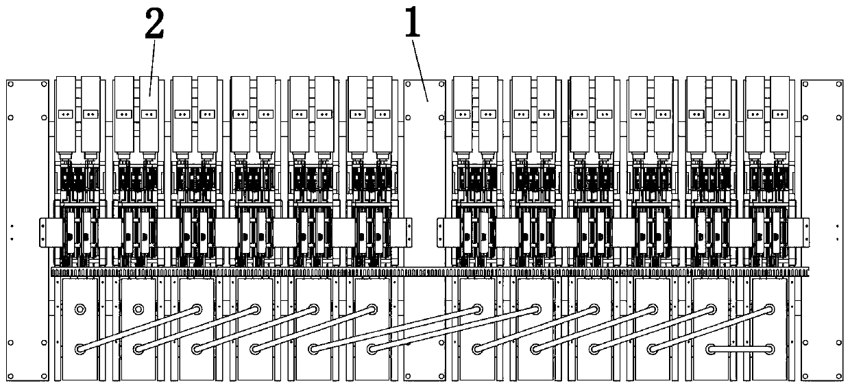
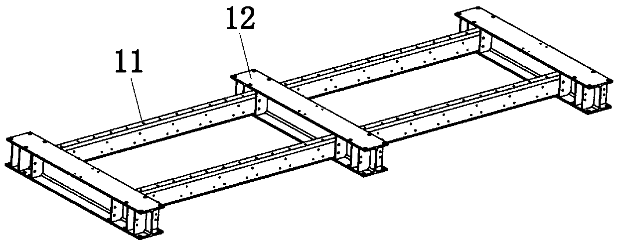
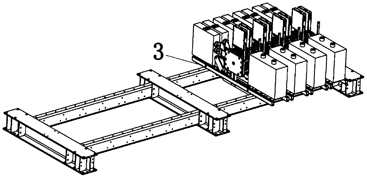
[0051] The valve module structure of the DC energy consumption device is as follows: figure 1 As shown, it consists of a rectangular frame 1 and a sub-module 2, such as figure 2 As shown, the rectangular frame is assembled by three metal beams 12 and four insulating beams 11, such as image 3 As shown, the submodule 2 is assembled with the insulating beam 11 through the submodule mounting part 3 . Each valve module consists of 12 submodules 2 .

[0052] The submodule structure is like Figure 4 to Figure 7 As shown, components such as capacitors 21, diodes, IGBTs, resistors, boards 26 and multiple conductive plates are installed on the sub-module mounting parts.

[0053] Structural submodule topology such as Figure 8As shown, the following will be further explained according to this topology structure, which is composed of two levels of electrical sub-modules, in which diode 1, diode 2, diode 3, diode 1', diode 2', and diode 3' are all diodes, and IGBT-1 and Whether th...


PUM


Abstract

The invention provides a direct-current energy consumption device valve module. The direct-current energy consumption device valve module comprises a rectangular frame and a series sub-module arrangedon one side of the rectangular frame. Each sub-module comprises electrical modules which are connected in series. The direct-current energy consumption device valve module is in electrical connection, and the structure is easy to assemble and maintain.

Description

technical field [0001] The invention relates to the technical field of power electronics, in particular to a valve module of a DC energy consumption device. Background technique [0002] The direct current transmission line can efficiently and conveniently transmit a large amount of electric energy from the energy base to the load center. For the direct current transmission project in operation, the electric energy consumed by the receiving end is balanced with the electric energy sent by the sending end , the voltage and operating frequency of the power grid at the sending end remain constant. When the power system at the receiving end is disturbed or fails and cannot absorb the electric energy sent by the sending end, the voltage and frequency of the sending end power grid will be disturbed, and this disturbance can be reduced by quickly adjusting the output of the generator; if the power supply at the sending end is For thermal or hydroelectric generators, the output of ...

Claims


Application Information

Patent Timeline
IPC IPC(8): H02J3/36H02J3/24
CPCH02J3/24H02J3/36H02J2003/365Y02E60/60
Inventor 王治翔高冲李云鹏周建辉张晓龙王成昊乔丽
Owner GLOBAL ENERGY INTERCONNECTION RES INST CO LTD
Learn More