Battery management system and method therefor

A battery management system and battery management technology, applied in the field of management systems, can solve problems such as high failure rate, high cost of battery management systems, and increased circuit area.

Active Publication Date: 2022-02-18
FUN WIND ENERGY
View PDF0 Cites 0 Cited by
  • Summary
  • Abstract
  • Description
  • Claims
  • Application Information

AI Technical Summary

Problems solved by technology

Among them, lithium batteries are widely used nowadays, and the existing lithium battery management system monitors the battery voltage by measuring the voltage between the positive and negative terminals of the battery regardless of the state of charge or discharge. The voltage is the sum of the voltage corresponding to the electromotive force of the battery plus the voltage drop generated on the internal resistance of the battery when the current flows. Therefore, the voltage measured between the positive and negative terminals of the battery will vary with the measurement time. Affected by the size of the current used, regardless of the current used by the energy storage device or the vehicle is changing at any time, but the current management system measures the voltage of each battery using a sequential measurement method, not measuring the voltage of each point at the same time, especially for lithium-iron batteries. When in use, the voltage drop from full load to 90% of the use is less than 10% relative to the voltage drop, and the minimum difference in the corresponding current change is often more than 10 times, so this current change is reflected in the internal resistance of the battery. The change in voltage drop is several times greater than the change in electromotive force generated by the difference in battery power. As a result, under the condition of such battery power changes, the current voltage monitoring cannot correctly measure the battery status.
[0004] Furthermore, in the charging or discharging process of the existing battery management system, if one (or several) batteries are fully charged, the charge balance function will be activated to wait for the other batteries to be fully charged before cutting off the power. If these balancing devices To completely fill the battery demand, a lot of energy must be consumed. In the battery management of low-power battery packs, the impact is relatively low, such as the battery management system of laptops or notebook computers (when the power is about 100 watts, the load does not change much). However, when the power of the battery used by the energy storage device or the vehicle exceeds several thousand watts, to fully meet the battery demand, the battery management system needs a very high power value, so the cost of the battery management system is high and the volume will increase significantly , will cause a lot of heat, so it is difficult for the current marketed products to meet the above-mentioned higher power requirements. In addition, in the process of use, as long as the battery with a small storage capacity in the battery pack is fully discharged, the entire battery pack cannot be used. Continue to use, so a lot of energy is wasted when charging, and the battery can't be used even if it is overcharged
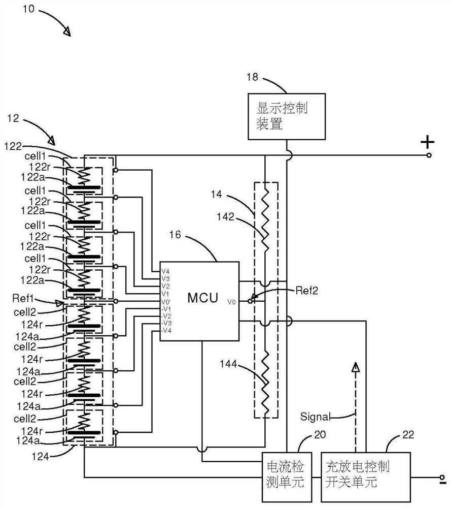
[0005] In addition, the high-voltage battery used in electric vehicles or hybrid vehicles is a battery pack formed by connecting multiple batteries in series. The high voltage is obtained by connecting the batteries in series. In this way, each battery is equipped with a balancing module or a monitoring module, which will As a result, the battery management system needs a large-area circuit to set up a plurality of balancing modules or monitoring modules to monitor the batteries at each level. Such a conventional battery management system will increase the circuit area and increase the circuit complexity.
[0006] The circuit structure of the existing battery management system is not easy to accurately judge the overcharge and discharge status of the battery pack, and the circuit is complicated. When the balance function is activated, a large amount of energy will be consumed and high heat will be generated. Therefore, a large heat dissipation device is required, otherwise the failure rate will be reduced. High, resulting in high cost of the existing battery management system and a lot of energy wasted in the charging and discharging process. In addition, in the case of inaccurate measurement of the battery state, the battery is placed on the edge of high voltage charging or over-discharging. long, resulting in shortened battery life

Method used


Image

  • Battery management system and method therefor
  • Battery management system and method therefor
  • Battery management system and method therefor

Examples


Embodiment Construction

[0057] In order to make the structural features of the present invention and the achieved effects have a further understanding and recognition, preferred embodiments and detailed descriptions are specially used, which are described as follows:

[0058] Hereinafter, the present invention will be described in detail by illustrating various embodiments of the present invention by means of drawings. Inventive concepts may however be embodied in many different forms and should not be construed as limited to the illustrative embodiments set forth herein.

[0059] The present invention breaks the conventional way that each battery in the battery module is equipped with a control circuit to detect the electrical properties of the battery, thus providing a battery management method, the user can switch the detected battery through a single control circuit through the Wheatstone bridge measured battery.

[0060] First, see figure 1 , which is a system diagram of an embodiment of the p...


PUM


Abstract

The invention discloses a battery management system and its method, which provide a battery pack with different levels of batteries that can be individually managed, and when any battery is about to be saturated, the charging current is reduced to avoid oversaturated charging until the set charging capacity is reached. Immediately stop charging, do not do balance charging to avoid oversaturated charging, and avoid damaging battery life.

Description

technical field [0001] The present invention relates to a management system and its method, in particular to a battery management system and its method. Background technique [0002] Generally speaking, the safety protection items that the existing battery management system can provide include charging overvoltage protection, charging overcurrent protection, discharging overheating protection, charging overheating protection, charging time protection and so on. When the battery management system implements charging overvoltage protection, the battery management system will activate the protection mechanism when the battery voltage exceeds a voltage threshold during charging, such as cutting off the charging switch of the battery, and release it when the voltage drops below the voltage threshold protection mechanism. [0003] With the rapid development of electronic technology, high-voltage series battery packs have been widely used in electric vehicles, hybrid vehicles, and...

Claims


Application Information

Patent Timeline
Patent Type & Authority Patents(China)
IPC IPC(8): H02J7/00
CPCH02J7/0019
Inventor 李季霖黄伟豪
Owner FUN WIND ENERGY
Why Eureka
Try Eureka