Energy-saving direct-current charging pile

A technology of DC charging piles and charging piles, which is applied in the field of electric power, can solve problems such as increased power consumption of charging piles, shortened service life of batteries, easy drumming, and aging, and achieves the goals of improving service life, saving energy, and achieving heat preservation Effect

Pending Publication Date: 2020-06-12
湖南省润诚达新能源科技股份有限公司
View PDF0 Cites 0 Cited by
  • Summary
  • Abstract
  • Description
  • Claims
  • Application Information

AI Technical Summary

Problems solved by technology

[0002] The function of the charging pile is similar to the fuel dispenser in the gas station. It can be fixed on the ground or wall, and installed in the parking lot or charging station of public buildings and residential areas. The input end of the charging pile is directly connected to the DC power grid, and the output end is equipped with charging The plug is used to charge electric vehicles, but the standby state of the charging pile will consume the power of the charging pile instead, resulting in an increase in the power consumption of the charging pile, which does not meet the current concept of energy saving and environmental protection. Instead, solar panels are used to supply power to the charging pile. Without protection for the battery, the battery is prone to swelling and aging after being repeatedly affected by radiation for a long time, which will shorten the service life of the battery. However, this kind of solar panel will be covered with a lot of dust when it is used for a long time. If it is not used for a long time Cleaning will greatly affect the power generation efficiency and the service life of solar panels, and solar panels are generally installed on the top of charging piles, and the cleaning of solar panels will consume a lot of manpower, financial and material resources

Method used


Image

  • Energy-saving direct-current charging pile
  • Energy-saving direct-current charging pile
  • Energy-saving direct-current charging pile

Examples


Embodiment

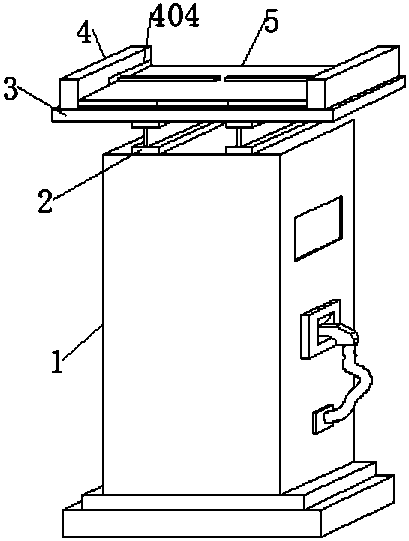
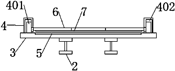
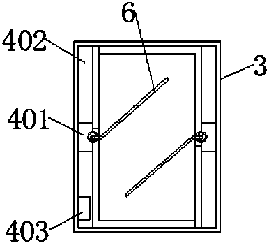
[0019] Example: see Figure 1-4 Among them, an energy-saving DC charging pile provided in this embodiment includes a charging pile 1, a bracket 2 is arranged above the charging pile 1, a support frame 3 is arranged above the bracket 2, and both sides of the support frame 3 are arranged There is a heat insulation shield 4, the upper surface of the support frame 3 is provided with a solar panel 5, and the solar panel 5 is located between the two heat insulation shields 4, and the middle end of the heat insulation shield 4 is provided with a rain A scraper motor 401, batteries 402 are provided on both sides of the heat shield 4, a PLC controller 403 is provided inside the support frame 3, a wiper arm 6 is provided at one end of the wiper motor 401, and a wiper arm 6 is provided at one end of the wiper motor 401. The motor 401 is connected to the PLC controller 403 by signals, and the wiper motor 401 and the PLC controller 403 are both connected to the battery 402 through wires. ...


PUM


Abstract

The invention provides an energy-saving direct-current charging pile, which comprises a charging pile, wherein a bracket is arranged above the charging pile, a supporting frame is arranged above the bracket, heat insulation protective covers are arranged on the two sides of the supporting frame, a solar cell panel is arranged on the upper surface of the supporting frame and located between the twoheat insulation protective covers, a wiper motor is arranged at the middle end in each heat insulation protective cover, storage batteries are arranged on the two sides of the heat insulation protective covers, a PLC is arranged in the supporting frame, a wiper arm is arranged at one end of the wiper motor, and a lint layer is tightly attached to the lower surface of the wiper arm. According to the invention, heat energy is converted into electric energy through the solar cell panel, the electric energy is stored in the storage battery, the electric quantity of the charging pile is supplemented, and thus the purpose of saving energy is achieved. The wiper arm moves back and forth to clean dust on the surface of the solar cell panel, and the efficiency of solar photoelectric conversion isimproved.

Description

technical field [0001] The invention relates to the field of electric power technology, in particular to an energy-saving DC charging pile. Background technique [0002] The function of the charging pile is similar to the fuel dispenser in the gas station. It can be fixed on the ground or wall, and installed in the parking lot or charging station of public buildings and residential areas. The input end of the charging pile is directly connected to the DC power grid, and the output end is equipped with charging The plug is used to charge electric vehicles, but the standby state of the charging pile will consume the power of the charging pile instead, resulting in an increase in the power consumption of the charging pile, which does not meet the current concept of energy saving and environmental protection. Instead, solar panels are used to supply power to the charging pile. Without protection for the battery, the battery is prone to swelling and aging after being repeatedly a...

Claims


Application Information

Patent Timeline
IPC IPC(8): B60L53/31B60L53/51H02S40/10H02S40/38H02J7/35B08B1/00
CPCB60L53/31B60L53/51H02S40/10H02S40/38B08B1/143Y02E10/50Y02T10/70Y02T10/7072Y02T90/12Y02E70/30
Inventor 王浩郭峰
Owner 湖南省润诚达新能源科技股份有限公司
Why Eureka
Try Eureka