Upper shell assembling machine

A technology for assembling machines and casings, applied in the directions of conveyor objects, transportation and packaging, can solve problems such as affecting product quality, dislocation of the circumferential position of the upper casing, affecting production costs and efficiency, and avoiding accidental movement.

Pending Publication Date: 2020-06-12
CHONGQING LINGLONG AUTOMATION EQUIP CO LTD
View PDF0 Cites 4 Cited by
  • Summary
  • Abstract
  • Description
  • Claims
  • Application Information

AI Technical Summary

Problems solved by technology

At present, the circumferential position of the upper casing is mostly adjusted manually and then transferred to the next station. It can be seen that this kind of low-automation operation will not only increase the labor intensity of the operator, but also greatly affect the assembly efficiency.
In addition, after the manual or automated assembly operation is completed, the upper casing may still be dislocated in the circumferential direction. If it is directly entered into the next process (welding process), it is very likely to affect the product quality and cause unqualified products, which seriously affects the production cost and efficiency

Method used


Image

  • Upper shell assembling machine
  • Upper shell assembling machine
  • Upper shell assembling machine

Examples


Embodiment 1

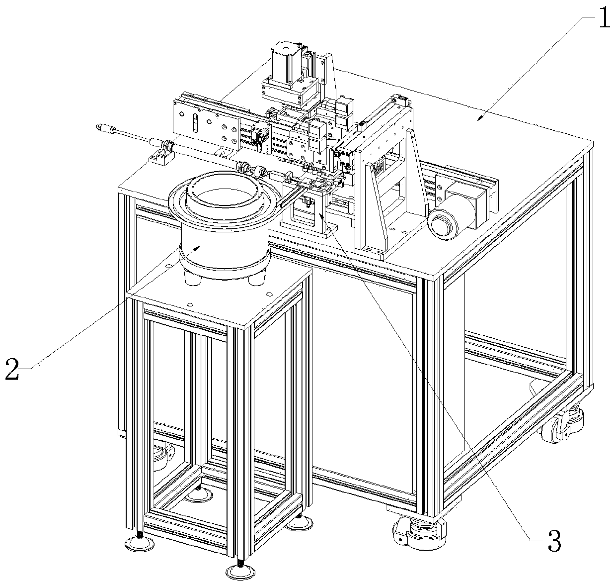
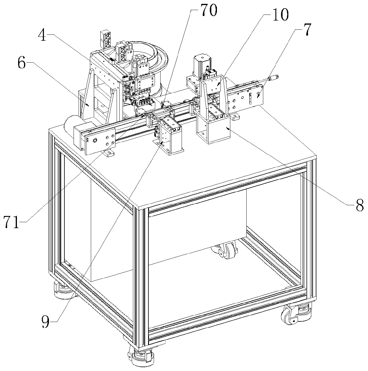
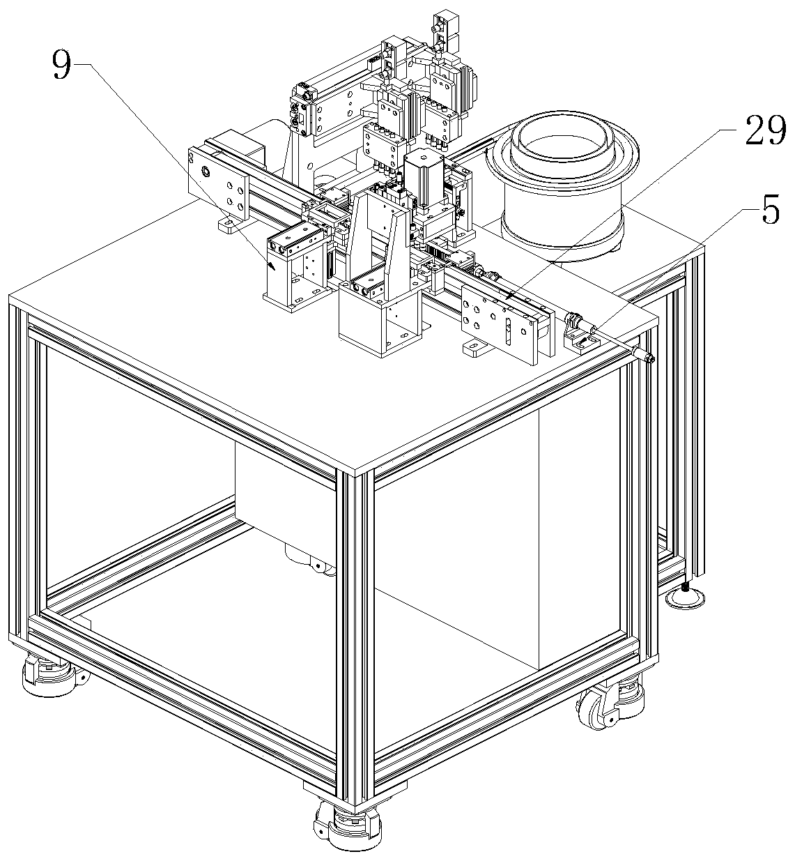
[0083] Such as Figure 1 to Figure 28 As shown, the upper casing assembly machine includes a support platform 1 on which an upper casing vibration plate 2, an assembly transfer support frame 3, an assembly correction mounting frame 4, an assembly drive mounting frame 5, and an assembly feeding support frame 6 are installed. , transmission frame 7, error-proof positioning support frame 8, assembly positioning support frame 9 and error-proof driving support frame 10;

[0084] A separation drive device 11 is installed on the assembly transfer support frame 3, and the output end of the separation drive device 11 is connected with a feeding transfer plate 12, and several assembly transfer devices that can communicate with the output end of the upper casing vibration plate 2 are arranged on the feed transfer transfer plate 12. slot 13;

[0085] Assembling and rectifying the mounting frame 4 is rotatably connected with several groups of correcting components corresponding to several...

Embodiment 2

[0113] This embodiment makes the following further limitations on the basis of Embodiment 1: the positioning drive device 40 is installed on the error-proof positioning support frame 8 and the assembly positioning support frame 9, and the output end of the positioning drive device 40 is connected with A jig positioning frame 41 that can move up and down. The jig positioning frame 41 has a jig positioning block 42 located above the error-proof positioning and placing plate 31 or the assembly positioning and placing plate 30 .

[0114] In order to realize the positioning of the revolving jig by the fixture positioning frame, preferably, the fixture positioning frame 41 has a positioning connecting plate 67 connected to the output end of the positioning drive device 40, and the two ends of the positioning connecting plate 67 are connected with a positioning support plate 68 , the top ends of the two positioning support plates 68 are connected with the jig positioning block 42 .

...

Embodiment 3

[0120] This embodiment makes the following further limitations on the basis of Embodiment 1: the correction transmission gear 43 is connected to the correction rotating sleeve 2 of each set of correction components;

[0121] The output end of the correction driving device 23 is connected with a correction transmission rack 44 meshing with the correction transmission gear 43 .

[0122] In this embodiment, for structural optimization, the correction transmission gear 43 should be located below the correction outer positioning member 21 . The correction transmission gear 43 can be sleeved on the correction rotation sleeve 15, and fixed by fastening screws.

[0123] Preferably, in order to observe the cooperation between the correction transmission gear 43 and the correction transmission rack 44 , an observation window 72 may be provided on the assembly correction installation frame 4 . In order to protect the operation of the outer orthosis sleeve 19 , the orthotic installation ...


PUM


Abstract

The invention provides an upper shell assembling machine. The upper shell assembling machine comprises a supporting platform, a vibration plate, a transfer support frame, a driving device mounting frame, a correction supporting frame and a feeding supporting frame are mounted on the supporting platform; a separation driving device is mounted on the transfer supporting frame, and a feeding transferplate is connected to the output end of the separation driving device; a plurality of groups of correction assemblies are rotatably connected to the correction supporting frame; a correction drivingdevice is mounted on the driving device mounting frame, and a transmission rack is connected to the output end of the correction driving device; and the feeding driving device is mounted on the feeding supporting frame, and a suction nozzle assembly is connected to the output end of the feeding driving device. According to the upper shell assembling machine, the feeding transfer plate is arranged,scattered upper shells can be placed in a transfer tank orderly one by one; the multiple correction assemblies and the transmission rack are arranged, the circumferential positions of the multiple upper shells can be adjusted at the same time; and a suction nozzle is arranged, and the feeding work of the upper shells in the correction process can be achieved.

Description

technical field [0001] The invention relates to the technical field of mobile phone linear motors, in particular to an upper casing assembly machine. Background technique [0002] The upper casing is an important part of the linear motor of the mobile phone, and it can work together with the lower casing to protect the motor. The upper casing is mostly a cylindrical cover structure, which has an accommodation cavity that can accommodate the mover (leaf spring, vibrator, magnetic sleeve and magnetic steel) and the stator (FPC (flexible circuit board) flexible wiring piece and coil), and The bottom end is provided with an accommodating opening capable of communicating with the accommodating cavity. The lower casing mostly includes a disc-shaped shell, and the side wall of the shell has connecting pieces extending radially outward. The housing can cover the receiving opening. In order to improve the stability of the connection between the upper casing and the lower casing, t...

Claims


Application Information

Patent Timeline
Patent Type & Authority Applications(China)
IPC IPC(8): B65G47/14B65G47/24B65G47/91B65G47/22
CPCB65G47/1421B65G47/24B65G47/912B65G47/22
Inventor 万世超江锋
Owner CHONGQING LINGLONG AUTOMATION EQUIP CO LTD
Why Eureka
Try Eureka