A steel structure residual stress measuring instrument and using method thereof

A residual stress, steel structure technology, applied in the direction of force/torque/work measuring instrument, measuring device, mechanical measuring device, etc., can solve the problems such as the deviation of the measuring cone head from the center of the measuring hole, the inability to obtain the residual stress, and the large restoring force. , to achieve the effect of easy disassembly and replacement, low production cost and simple structure

Active Publication Date: 2021-02-05
TSINGHUA UNIV
View PDF6 Cites 0 Cited by
  • Summary
  • Abstract
  • Description
  • Claims
  • Application Information

AI Technical Summary

Problems solved by technology

[0003] However, when using the cutting method to measure the residual stress of steel structures, the existing hand-held strain gauges cannot accurately measure the longitudinal residual stress near the junction of cross-section plates such as H-shaped steel, I-shaped steel, T-shaped steel, and angle steel, because The existing hand-held strain gauges are large in size and are limited by the measurement space. It is generally impossible to accurately measure the initial spacing of each pair of small holes near the intersection of the plates before the component is cut, so the accurate residual stress here cannot be obtained; Especially for sections with small cross-sections, the number of steel strips that can be cut on each plate is not much. If there are still some steel strips that cannot provide accurate residual stress measurement results, it will not be possible to obtain a reliable cross-sectional residual stress distribution in the end. ; Moreover, the stiffness of the spring used in the buffer system of the existing handheld strain gauge is too large, and the restoring force during the measurement is relatively large, which causes the measuring cone to deviate from the center of the measuring hole and affects the measurement accuracy

Method used


Image

  • A steel structure residual stress measuring instrument and using method thereof
  • A steel structure residual stress measuring instrument and using method thereof
  • A steel structure residual stress measuring instrument and using method thereof

Examples


Embodiment Construction

[0042] In order to make the objectives, technical solutions and advantages of the present invention clearer, the technical solutions in the embodiments of the present invention will be described in more detail below in conjunction with the drawings in the embodiments of the present invention. In the drawings, the same or similar reference numerals denote the same or similar elements or elements having the same or similar functions throughout. The described embodiments are some, but not all, embodiments of the invention.

[0043]Based on the embodiments of the present invention, all other embodiments obtained by persons of ordinary skill in the art without creative efforts fall within the protection scope of the present invention.

[0044] The embodiments and directional words described below by referring to the figures are exemplary and are intended to explain the present invention, but should not be construed as limiting the present invention.

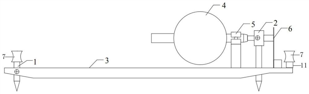
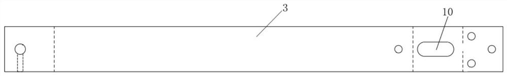
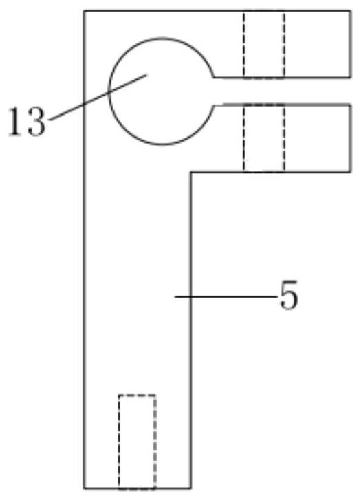
[0045] Such as Figure 1-5 A...


PUM


Abstract

The invention proposes a steel structure residual stress measuring instrument and its use method. The measuring instrument includes a fixed measuring cone, a sliding measuring cone, a metal bracket, a dial indicator, a clamping bracket and a buffer spring system, a clamping bracket, a fixed measuring Both the cone head and the buffer spring system are fixed on the metal bracket, and the dial gauge is placed on the metal bracket side, and the thickness of the dial is similar to or the same as the width of the metal bracket; the sliding measuring cone can be inserted into the sliding hole of the metal bracket. Sliding freely, its left end is connected to the end of the measuring rod of the dial indicator, and the right end is close to the buffer spring system. The measuring instrument is also equipped with a standard hole distance ruler and a temperature correction ruler with the same structure and size. The former is used as a reference ruler, and the latter is used to correct the influence of temperature changes on the hole distance of the small holes to be measured. The measuring instrument of the invention has a simple structure and can accurately measure the magnitude of residual stress near the junction of plates; the measuring restoring force is small, and the measuring cone will not deviate from the center of the measuring hole, and the measuring accuracy will not be affected.

Description

technical field [0001] The invention belongs to the technical field of steel structure stress measurement, and in particular relates to experimental research on the distribution of residual stress in a section of a steel structure, in particular to a steel structure residual stress measuring instrument and a use method thereof. Background technique [0002] Residual stress distribution is one of the important factors affecting the stability of steel structures, and has a very important impact on the fatigue performance, brittle fracture and stress corrosion of steel structures. The research on the residual stress distribution of component sections is one of the important research topics in the field of steel structures. At present, the cutting method is usually used to measure the residual stress distribution of steel structures. When using the cutting method to measure the residual stress of a steel structure, firstly drill several pairs of small holes on the steel member, ...

Claims


Application Information

Patent Timeline
Patent Type & Authority Patents(China)
IPC IPC(8): G01L5/00G01B5/14
CPCG01B5/143G01L5/0047
Inventor 施刚张紫千王蠡钧
Owner TSINGHUA UNIV
Why Eureka
Try Eureka