Double-sided flow field for polar plate for improving material distribution uniformity of fuel cell

A technology with uniform distribution and fuel cells, applied in fuel cell components, fuel cells, circuits, etc., can solve the problems of low material concentration, large flow resistance, and difficulty in discharging water droplets, so as to improve mass transfer efficiency and improve consistency. , the effect of small flow resistance

Active Publication Date: 2020-06-12
DALIAN INST OF CHEM PHYSICS CHINESE ACAD OF SCI
View PDF6 Cites 2 Cited by
  • Summary
  • Abstract
  • Description
  • Claims
  • Application Information

AI Technical Summary

Problems solved by technology

[0003] Although the flow resistance of the parallel flow field is small, the pressure of adjacent grooves is similar, and the mass transfer effect under the ridge is poor
Especially in the direct alcohol fuel cell cathode, the parallel flow field is prone to water flooding, the water droplets block the groove and it is difficult to discharge, and the mass transfer of the material in the blocked area is limited, resulting in uneven material distribution at the battery reaction interface and reducing battery performance.
[0004] Although the serpentine flow field has a good drainage effect for the cathode flow field, the groove stroke is long and the pressure drop is large, which will increase the energy consumption of the fuel cell gas supply device; at the same time, the material concentration in the downstream area of ​​the groove is low, especially in large The problem of poor concentration uniformity in the area flow field is more obvious
[0005] Although the interdigitated flow field has a good mass transfer effect under the ridge, the flow resistance is large because the inlet and outlet of the flow field groove are not connected, which increases the power consumption of auxiliary components of the fuel cell system and reduces the efficiency of the fuel cell system

Method used


Image

  • Double-sided flow field for polar plate for improving material distribution uniformity of fuel cell
  • Double-sided flow field for polar plate for improving material distribution uniformity of fuel cell
  • Double-sided flow field for polar plate for improving material distribution uniformity of fuel cell

Examples


Embodiment

[0029] 1. The bipolar plate is made of stainless steel sheet, and the groove is formed on the front and back of the stainless steel plate by stamping process.

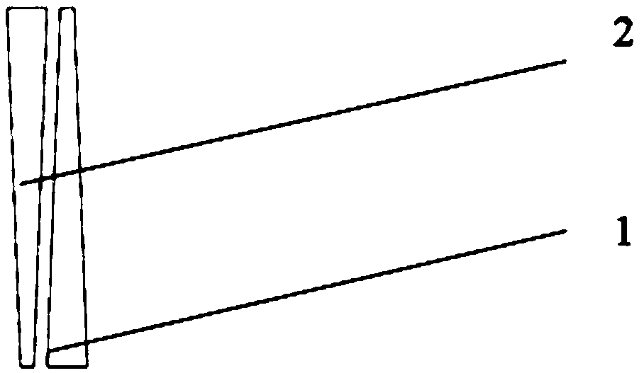
[0030] 2. The pole plate proves that the flow field is set with 3 sets of parallelogram grooves in the horizontal direction and 3 sets of parallelogram grooves in the vertical direction, arranged in a matrix, such as figure 2 , the longitudinal staggered spacing is 4.5mm; the isosceles trapezoidal groove, the waist length is 40mm, the short side is 1.5mm, the short side section depth is 0.5mm, the long side is 4.5mm, and the long side section depth is 0.5mm; the reverse flow field plane is a parallelogram groove The short side of the groove is 1.5mm, and the long side is 40mm.
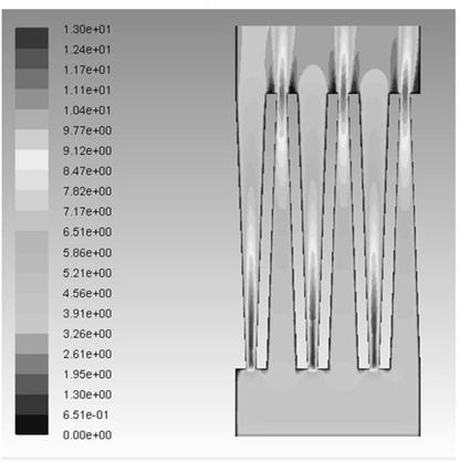
[0031] 3. The cross-sectional area of ​​the channel on the long side of the trapezoid is larger than that on the short side of the trapezoid. The velocity of the fluid entering the channel on the short side of the trapezoid increases and the p...


PUM


Abstract

The invention relates to a double-sided flow field for a polar plate for improving the material distribution uniformity of a fuel cell, the polar plate is formed by stamping a stainless steel flat plate, grooves sunken towards the inside of the plate surface are formed in the front surface and the back surface of the stainless steel plate, and ridges protruding towards the outside of the plate surface are arranged on the back surface corresponding to the grooves; and the reverse flow field is formed by sequentially arranging a column of flow fields or more than two columns of flow fields whichare sequentially arranged at intervals by long-strip-shaped bulges from top to bottom. The flow field is suitable for a thin plate stamping process, multi-stage disturbing fluid is arranged on the front face and the back face, and material distribution uniformity is good; the parallel arrangement structure improves the mass transfer efficiency; and mass transfer strengthening effect under the ridges of the parallelogram groove group is good.

Description

technical field [0001] The invention belongs to the improvement technology of fuel cell device. To be precise, it belongs to the improved technology of flow field of proton exchange membrane fuel cell. Background technique [0002] The flow field structure of proton exchange membrane fuel cell has parallel type, serpentine type, interdigitated type and so on. [0003] Although the flow resistance of the parallel flow field is small, the pressure of adjacent grooves is similar, and the mass transfer effect under the ridge is poor. Especially in the direct alcohol fuel cell cathode, the parallel flow field is prone to water flooding, the water droplets block the groove and it is difficult to discharge, and the mass transfer of materials in the blocked area is limited, resulting in uneven material distribution at the battery reaction interface and reducing battery performance. [0004] Although the serpentine flow field has a good drainage effect for the cathode flow field, t...

Claims


Application Information

Patent Timeline
Patent Type & Authority Applications(China)
IPC IPC(8): H01M8/026H01M8/0265
CPCH01M8/026H01M8/0265Y02E60/50
Inventor 孙海张盟赵世雄孙公权
Owner DALIAN INST OF CHEM PHYSICS CHINESE ACAD OF SCI
Why Eureka
Try Eureka