Inductance parameter obtaining method and device

A technology of inductance parameters and acquisition methods, which is applied in the direction of controlling electromechanical transmission devices, electrical components, and controlling generators, can solve problems such as unproposed solutions, secondary errors of inductance difference, and influence of motor torque accuracy, etc., and achieve reduction error, solve the effect of large error, and improve torque accuracy

Inactive Publication Date: 2020-06-12
BEIJING JINGHUAN EQUIP DESIGN RES INST CO LTD +1
View PDF8 Cites 0 Cited by
  • Summary
  • Abstract
  • Description
  • Claims
  • Application Information

AI Technical Summary

Problems solved by technology

For the separately identified d-axis and q-axis inductance, no matter which method is used to identify the d-axis inductance and q-axis inductance, there will be a certain error. After making the difference, it will cause a s

Method used


Image

  • Inductance parameter obtaining method and device
  • Inductance parameter obtaining method and device
  • Inductance parameter obtaining method and device

Examples


Embodiment 1

[0029] According to an embodiment of the present invention, an embodiment of an inductance parameter acquisition method is provided. It should be noted that the steps shown in the flow chart of the accompanying drawings can be executed in a computer system such as a set of computer-executable instructions, and, Although a logical order is shown in the flowcharts, in some cases the steps shown or described may be performed in an order different from that shown or described herein.

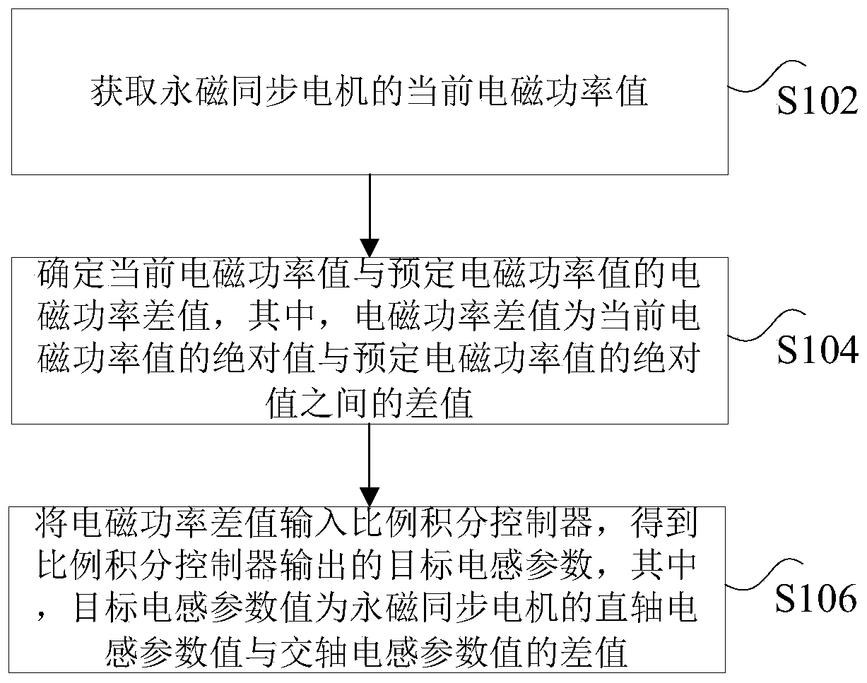
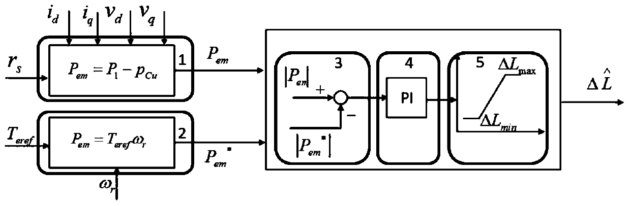
[0030] figure 1 is a flow chart of an inductance parameter acquisition method according to an embodiment of the present invention, such as figure 1 As shown, the method includes the following steps:

[0031] Step S102, obtaining the current electromagnetic power value of the permanent magnet synchronous motor;

[0032] Step S104, determining the electromagnetic power difference between the current electromagnetic power value and the predetermined electromagnetic power value, wherein the electromag...

Embodiment 2

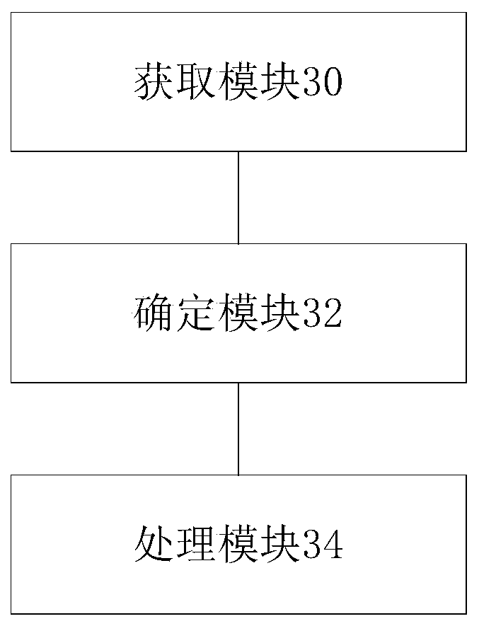
[0062] According to an embodiment of the present invention, an embodiment of a device for implementing the above-mentioned inductance parameter acquisition method is also provided, image 3 is a schematic structural diagram of an inductance parameter acquisition device according to an embodiment of the present invention, such as image 3 As shown, the above-mentioned inductance parameter acquisition device includes: an acquisition module 30, a determination module 32 and a processing module 34, wherein:

[0063] The obtaining module 30 is used to obtain the current electromagnetic power value of the permanent magnet synchronous motor; the determination module 32 is used to determine the electromagnetic power difference between the above-mentioned current electromagnetic power value and the predetermined electromagnetic power value, wherein the above-mentioned electromagnetic power difference is the current electromagnetic power value The difference between the absolute value o...


PUM


Abstract

The invention discloses an inductance parameter obtaining method and device. The method comprises the following steps: acquiring a current electromagnetic power value of the permanent magnet synchronous motor; determining an electromagnetic power difference value between the current electromagnetic power value and a predetermined electromagnetic power value, wherein the electromagnetic power difference value is a difference value between an absolute value of the current electromagnetic power value and an absolute value of the predetermined electromagnetic power value; inputting the electromagnetic power difference value into a proportional-integral controller to obtain a target inductance parameter output by the proportional-integral controller, wherein the target inductance parameter value is the difference value between the direct-axis inductance parameter value and the quadrature-axis inductance parameter value of the permanent magnet synchronous motor. According to the method, thetechnical problem that the torque precision of the permanent magnet synchronous motor is reduced due to the fact that an existing permanent magnet synchronous motor inductance parameter identificationmethod is large in error is solved.

Description

technical field [0001] The present invention relates to the technical field of permanent magnet synchronous motors, in particular to a method and device for acquiring inductance parameters. Background technique [0002] In this technical field, there are currently two identification methods for inductance parameters of permanent magnet synchronous motors: one is offline identification, and the other is online parameter identification. [0003] However, whether it is offline parameter identification or online parameter identification, the motor inductance is identified separately from the d-axis inductance and the q-axis inductance. But in some cases, it is not necessary to know the specific values ​​of d-axis inductance and q-axis inductance, but the difference between d-axis inductance and q-axis inductance is of interest. For example, the accuracy of the torque value obtained by calculation in the electric drive system of electric vehicles is only related to the accuracy ...

Claims


Application Information

Patent Timeline
IPC IPC(8): H02P21/14H02P25/022H02P6/08
CPCH02P6/08H02P21/14H02P25/022
Inventor 李二良赵大伟薛振东苏伟李金龙胡景林
Owner BEIJING JINGHUAN EQUIP DESIGN RES INST CO LTD
Why Eureka
Try Eureka