Multi-station can making equipment

A technology of station system and equipment, applied in the field of multi-station can making equipment, can solve the problems of low production efficiency, increase the danger of manual work, inaccurate positioning of the can body, and achieve the effect of high efficiency

Inactive Publication Date: 2020-06-16
关杨
View PDF0 Cites 1 Cited by
  • Summary
  • Abstract
  • Description
  • Claims
  • Application Information

AI Technical Summary

Problems solved by technology

However, the existing device for crimping stainless steel tanks has simple structure and single function, and the equipment can only complete the crimping operation of one tank body, and it is necessary to manually place the tank body in the crimping equipment, which will Increase the danger of manual work; and when the tank body needs to be processed with stretching flare, cone expansion, punching mouth, expansion ribs and other processes, the tank body needs to be positioned. The traditional can making machine is hugged by a manipulator Due to the large deviation of the can body, the...

Method used


Image

  • Multi-station can making equipment
  • Multi-station can making equipment
  • Multi-station can making equipment

Examples


Embodiment approach

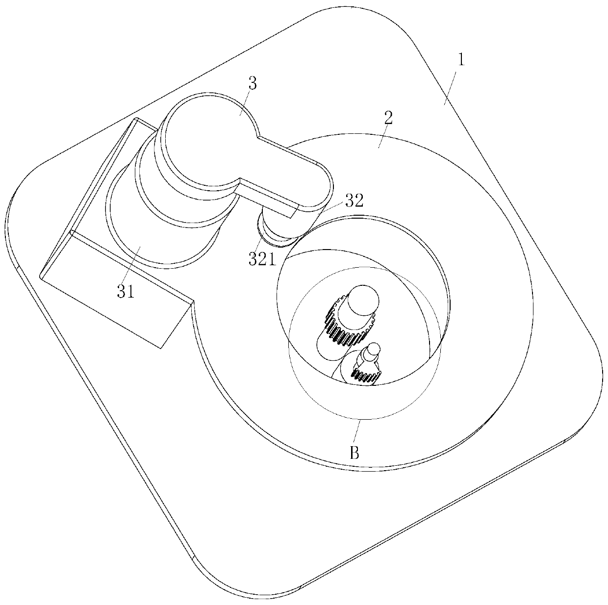
[0026] As a specific embodiment of the present invention, the No. 1 gear 211 is a sector gear with a center angle of 72 degrees; by setting the No. 1 gear 211 as a sector gear with 72 degrees, the non-stop operation of the No. 2 motor 21 is realized; When working, it takes 3-5 seconds to manually push the tank body into the clamping groove 411, and it also takes 4-6 seconds when the turntable 321 rolls out the crimping on the upper tank mouth of the tank body ; In order to control the time, some can making machines control the indirect rotation and stop of the motor, which will affect the service life of the motor. When the motor 21 rotates, the No. 2 motor 21 drives the No. 1 gear 211 to rotate, so that the No. 1 gear 211 and the No. 2 gear 221 are indirectly meshed. At the same time, the No. 1 disc 41 and the No. 2 disc 42 are indirectly transferred to the transfer tank body to realize the second gear. The non-stop rotation of No. 2 motor 21, thereby improving the service li...

specific Embodiment approach

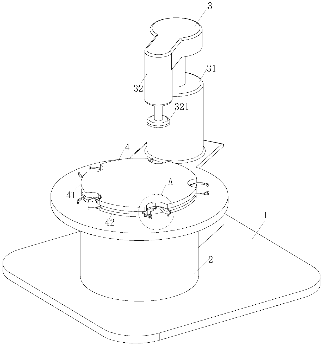
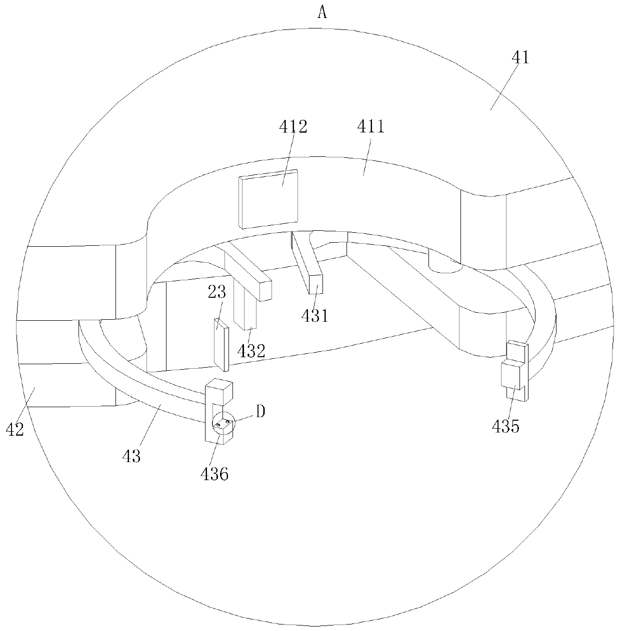
[0029] As a specific embodiment of the present invention, a copper plate 412 is provided on the side wall of the clamping groove 411 on the No. 1 disk 41, and the wires of the copper plate 412 are connected to an external power supply, and the two power lines on the copper plate 412 are respectively connected to the The clamping rod 43 is connected with the push rod 431; through the cooperation between the copper plate 412 and the push rod 431, the stability between the tank body and the clamping groove 411 is further enhanced; when working, the moving tank body is pushed into the clamping groove 411 , the tank body squeezes the push rod 431 on the clamping rod 43, and then the ends of the two push rods 431 are attached together. The current is passed through to generate magnetism, and then the tank body is adsorbed on the copper plate 412, so that the tank body is fastened in the clamping groove 411 again, so that when the first disc 41 and the second disc 42 transfer the tank...


PUM

PropertyMeasurementUnit
Center angleaaaaaaaaaa

Abstract

The invention belongs to the technical field of can making machines, and particularly relates to multi-station can making equipment. The multi-station can making equipment comprises a workbench, wherein a sleeve and an edge curling unit are arranged on the workbench, and the edge curling unit comprises an air cylinder and a first motor; and clamping rods are in arc shapes and are hinged into a clamping groove between a first disc and a second disc. According to the multi-station can making equipment, in an initial state, the distance between one ends of the adjacent clamping rods is larger than the diameter of the clamping groove, and the push rods fixedly connected to the other ends of the adjacent clamping rods are mutually close but do not make mutual contact; through cooperation of theedge curling unit and a clamping mechanism, edge curling of a can opening of a can body is achieved; and the can body is placed on the first disc and the second disc to be transferred, and a curled edge is curled out of an upper can opening of the can body, so compared with the mode that the can body is manually placed below a rotary plate, the can body can be transferred below the rotary plate through the first disc and the second disc, and accordingly efficiency is higher, and meanwhile the situation that danger occurs when a mechanical hand is manually touched due to the fact the can bodyis manually placed below the rotary plate can be avoided.

Description

technical field [0001] The invention belongs to the technical field of can making machines, in particular to a multi-station can making equipment. Background technique [0002] At present, in the processing of stainless steel tank products, it is necessary to curl the stainless steel tank to obtain finished stainless steel products. However, the existing device for crimping stainless steel tanks has simple structure and single function, and the equipment can only complete the crimping operation of one tank body, and it is necessary to manually place the tank body in the crimping equipment, which will Increase the danger of manual work; and when the tank body needs to be processed with stretching flare, cone expansion, punching mouth, expansion ribs and other processes, the tank body needs to be positioned. The traditional can making machine is hugged by a manipulator Due to the large deviation of the can body, the tight positioning and inaccurate alignment of the can body l...

Claims


Application Information

Patent Timeline
IPC IPC(8): B21D51/26
CPCB21D51/2623B21D51/2692
Inventor 关杨任磊
Owner 关杨
Why Eureka
Try Eureka