Low-air-pressure ejector device applied to mars wind tunnel

An ejector and low air pressure technology, which is applied in the direction of measuring devices, instruments, jet pumps, etc., can solve the problems of easy freezing of jet air, low gas density, and large gas consumption, so as to increase the highest wind speed and high ejection efficiency , The effect of small gas consumption

Pending Publication Date: 2020-06-16
中国航空工业集团公司哈尔滨空气动力研究所
View PDF0 Cites 5 Cited by
  • Summary
  • Abstract
  • Description
  • Claims
  • Application Information

AI Technical Summary

Problems solved by technology

[0004] In the traditional ejector, the diameter of the nozzle throat is relatively thick, the air supply pressure is high, and the gas consumption is large, which can make the nozzle outlet form a high Mach number. Under the action of the ejector, a high wind speed is formed in the test area
However, the Mars wind tunnel has extremely low air pressure, extremely low gas density, and low temperature. The use of traditional ejectors not only c

Method used


Image

  • Low-air-pressure ejector device applied to mars wind tunnel
  • Low-air-pressure ejector device applied to mars wind tunnel
  • Low-air-pressure ejector device applied to mars wind tunnel

Examples


Example Embodiment

[0020] Example 1

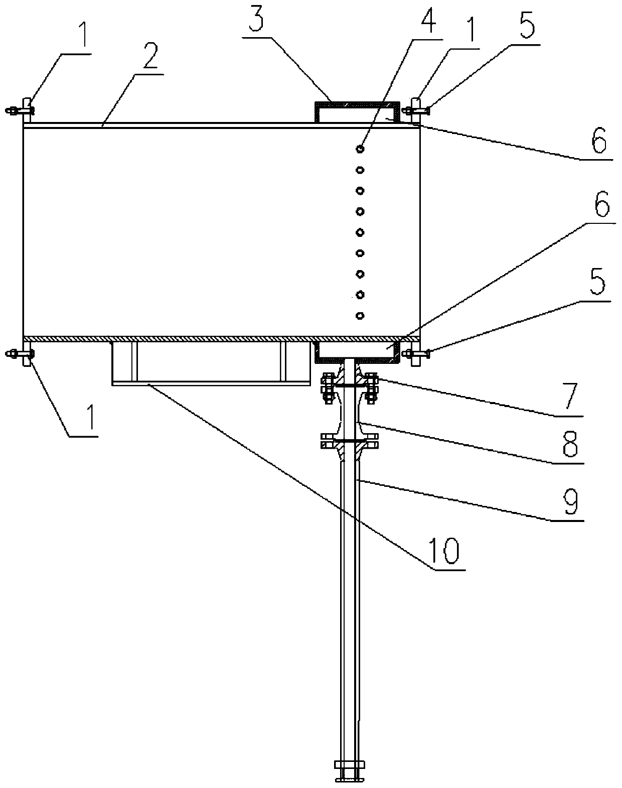
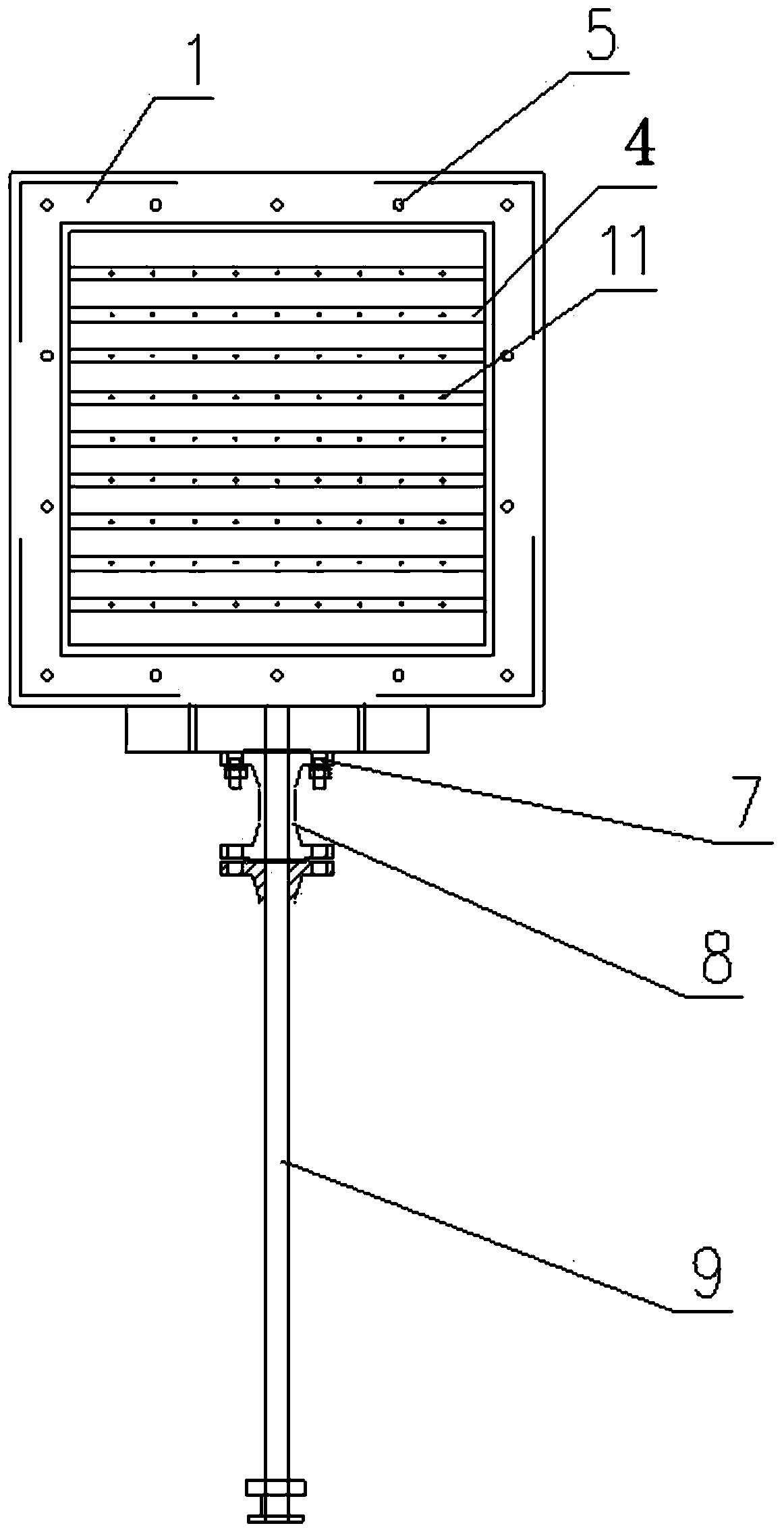
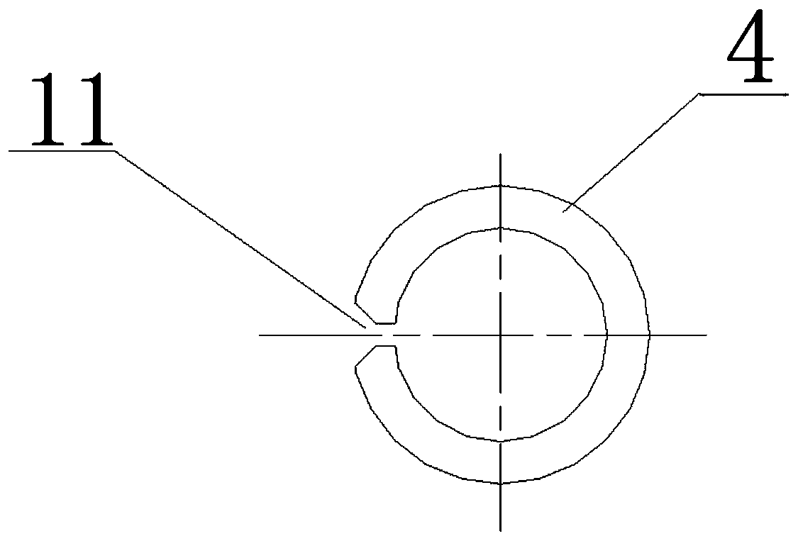
[0021] Such as Figure 1-4 As shown, a low-pressure ejector device applied to the Mars wind tunnel includes an ejector housing 2, an ejector chamber housing 3, an ejector chamber 6, a plurality of nozzles 4 and a gas supply pipeline 9. The gas supply pipeline 9 is in communication with the gas source. The ejector chamber shell 3 surrounds the ejector housing 2 in a circle, and is connected to the outer wall of the ejector to form a closed ejector chamber 6. The gas supply pipeline 9 In communication with the ejector chamber 6, a plurality of nozzles 4 are parallel to each other and pass through the ejector housing 2 radially at a certain interval. The head and tail of each nozzle 4 are connected to the ejector chamber respectively. 6 is connected, and a plurality of nozzles 11 are opened on the part of each nozzle 4 located inside the ejector housing 2. The nozzle 11 is a section of conical throat with a straight pipe. The throat adopts a 45-degree diffusion ...

Example Embodiment

[0022] Example 2

[0023] Combine Figure 4 , A low-pressure ejector device applied to the Martian wind tunnel, comprising an ejector housing 2, an ejector chamber housing 3, an ejector chamber 6, a plurality of nozzles 4 and a gas supply pipeline 9, The air supply pipeline 9 is in communication with an air source. The ejector chamber shell 3 surrounds the ejector housing 2 and is connected to its outer wall in a sealed manner to form a closed ejector chamber 6. The air supply pipeline 9 is connected to the ejector The ejector chamber 6 is connected, and a plurality of nozzles 4 are parallel to each other and pass through the ejector housing 2 radially at a certain interval. The head and tail of each nozzle 4 are respectively communicated with the ejector chamber 6 A plurality of nozzles 11 are opened on the part of each nozzle 4 located inside the ejector housing 2. The air source of the ejector device is stored in the buffer tank and introduced through the air inlet pipe 19, C...


PUM


Abstract

The invention aims to provide a low-air-pressure ejector device applied to a mars wind tunnel. The device comprises an ejector shell, an ejector cavity shell, an ejector cavity, multiple of spray pipes and an air supply pipeline; the air supply pipeline communicates with an air source; the ejector cavity shell surrounds the ejector shell for a circle and is connected with the outer wall of the ejector shell in a sealed mode to form the closed ejector cavity, and the air supply pipeline communicates with the ejector cavity; and the multiple of spray pipes are parallel to one another and penetrate through the ejector shell in the radial direction at certain intervals, the heads and the tails of the spray pipes communicate with the ejector cavity, and multiple of nozzles are formed in the parts, positioned in the ejector shell, of the spray pipes. Compared with a conventional ejector of the wind tunnel, the device has the beneficial effects that the ejection efficiency is extremely high,the same wind speed is formed, the gas consumption of the conventional ejector is large, the gas consumption of the device is small, the wind speed can be continuously formed for a long time, and thehighest wind speed can be remarkably increased.

Description

technical field [0001] The invention relates to a low-pressure ejector device applied to a Mars wind tunnel. Background technique [0002] The driving system of the atmospheric pressure low-speed wind tunnel is powered by a controllable motor and a fan driven by it. Another kind of temporary flushing high-speed wind tunnel, the air is pressurized and stored in the air storage tank in advance with a compressor, or the vacuum tank connected with the outlet pipe of the wind tunnel is evacuated with a vacuum pump, and the valve is quickly opened during the experiment to make the high-pressure air Enter the cave directly or through the ejector or suck the air into the cave by the vacuum tank, so there are various forms of blowing, ejection, suction and their combination. Generally, the Reynolds number is relatively high, and its working time can be changed by several seconds to tens of seconds. [0003] For the driving system of the Mars wind tunnel, its power driving system mu...

Claims


Application Information

Patent Timeline
IPC IPC(8): F04F5/16F04F5/44G01M9/06
CPCF04F5/16F04F5/44G01M9/06
Inventor 周文刘琛刘发刘立坤王振果王云祥张国友李丽芳闫继宏吴宜勇
Owner 中国航空工业集团公司哈尔滨空气动力研究所
Why Eureka
Try Eureka