
A signal channel calibration method and device based on correlation and least squares

A signal channel, least squares technology, applied in the field of signal channel calibration, can solve the problems of high test cost, many test instruments, large circuit gap, etc., to achieve the effect of improving competitiveness, expanding applications, and reducing dependence

Active Publication Date: 2022-03-29
NANJING CHANGFENG AEROSPACE ELECTRONICS SCI & TECH
View PDF0 Cites 0 Cited by
  • Summary
  • Abstract
  • Description
  • Claims
  • Application Information

AI Technical Summary

Problems solved by technology

High-speed digital oscilloscopes cannot perform high-precision measurement of multi-channel amplitude-phase characteristics, nor can they complete single-channel amplitude-phase linear measurement; mainstream spectrum analyzers on the market cannot meet the requirements of channel phase-frequency characteristic testing; vector network analyzers can realize single-channel High-precision test of channel amplitude and phase characteristics, but due to the small number of channels, it cannot meet the needs of simultaneous measurement of multi-channel receiver circuits; and software simulation analog circuits generally have a large gap with actual circuits, and the measurement results can only be used as a reference
In addition, the traditional test method needs to select corresponding test instruments according to the parameters to be tested. For active devices, auxiliary equipment such as power supply and control are required, and even an additional test bench is required. The entire test process requires many test instruments and high test costs. Test accuracy and repeatability test cannot be guaranteed, etc.

Method used


Image

  • A signal channel calibration method and device based on correlation and least squares
  • A signal channel calibration method and device based on correlation and least squares
  • A signal channel calibration method and device based on correlation and least squares

Examples


Embodiment 2

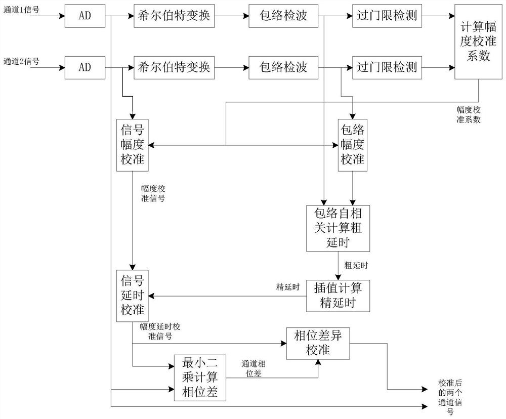
[0129] Embodiment 2: A signal channel calibration method based on correlation and least squares, the method flow chart of this embodiment is as follows Figure 7 shown, including:

[0130] Determine the transmission delay between the channel to be calibrated and the pre-selected reference channel, and complete the signal delay calibration of the channel to be calibrated according to the obtained transmission delay;

[0131] The initial phase of each channel is calculated by the least square method, and the phase difference between the channel to be calibrated and the reference channel is determined; according to the obtained phase difference, the signal phase difference calibration of the channel to be calibrated is completed. In this embodiment, existing technology can be used to determine the transmission delay between the channel to be calibrated and the pre-selected reference channel, and complete the signal delay calibration of the channel to be calibrated according to th...


PUM


Abstract

The invention discloses a signal channel calibration method and device based on correlation and least squares, which includes determining the transmission delay between the channel to be calibrated and a pre-selected reference channel, and completing the calibration process according to the obtained transmission delay. Channel signal delay calibration; the least square method is used to calculate the initial phase of each channel, and determine the phase difference between the channel to be calibrated and the reference channel; according to the obtained phase difference, complete the signal phase difference calibration of the channel to be calibrated. The present invention adopts a method based on correlation least squares, and designs a signal multi-channel amplitude-phase characteristic analysis calculation and calibration method. The method is based on the signal acquisition data of the same signal in each channel, and the signal amplitude is calculated by using the envelope correlation method. Delay information, the phase information of each channel signal is obtained through least square calculation, and the calibration of the amplitude and phase characteristics of each signal channel is automatically completed according to the measurement information, so as to achieve the consistency of the amplitude and phase characteristics of each signal channel.

Description

technical field [0001] The invention belongs to the technical field of signal channel calibration, and in particular relates to a signal channel calibration method and device based on correlation and least squares. Background technique [0002] As a powerful weapon in modern warfare, radar plays a vital role in aviation, aerospace, electronic warfare and other fields. [0003] With the rapid development of microelectronics technology and computer technology, the improvement of computer speed and the expansion of storage space, computer simulation technology has developed rapidly. Echo signal simulators have been widely used in the development, debugging, testing and performance evaluation of various synthetic aperture radar systems. There are many researches on radar simulator abroad, and many companies specialize in radar simulator research. For example, before the Earth Resources Satellites ERS-1 and ERS-2 launched by the European Space Agency, the Japanese Earth Resourc...

Claims


Application Information

Patent Timeline
Patent Type & Authority Patents(China)
IPC IPC(8): G01S7/40
CPCG01S7/4056G01S7/4065
Inventor 金科贾滨京刘杰张昊
Owner NANJING CHANGFENG AEROSPACE ELECTRONICS SCI & TECH
Learn More