
Inductor and electronic device

An inductor and current direction technology, applied in the field of circuits, can solve problems such as reducing the electromagnetic coupling of inductors, and achieve the effect of avoiding electromagnetic coupling and improving flexibility

Inactive Publication Date: 2020-06-16
SPREADTRUM COMM (SHANGHAI) CO LTD
View PDF2 Cites 0 Cited by
  • Summary
  • Abstract
  • Description
  • Claims
  • Application Information

AI Technical Summary

Problems solved by technology

[0005] The technical problem solved by the invention is how to reduce the electromagnetic coupling of the inductor without increasing the current consumption

Method used


Image

  • Inductor and electronic device
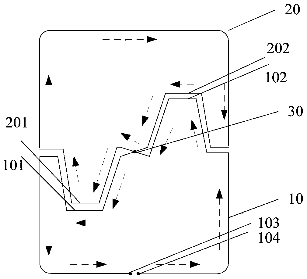
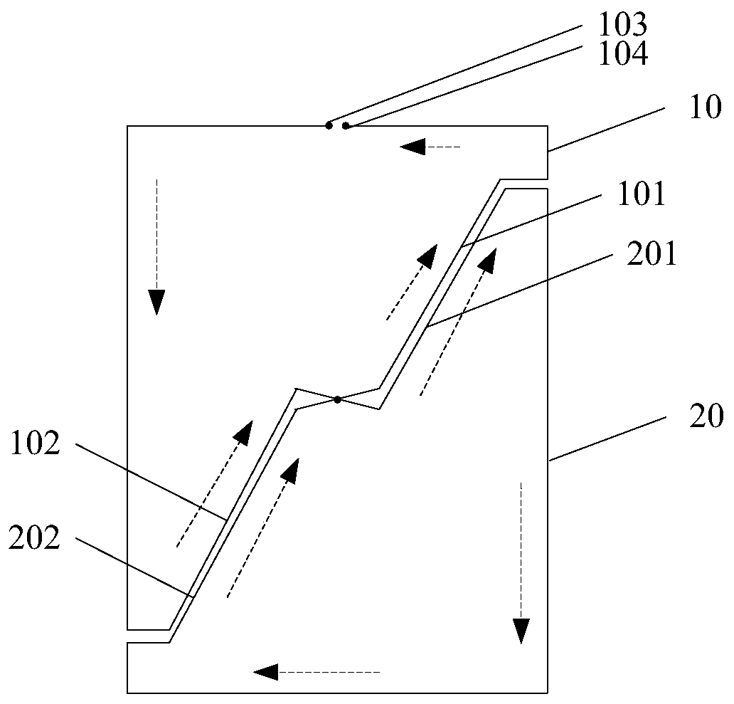
  • Inductor and electronic device

Examples


Embodiment Construction

[0021] As mentioned in the background art, the above solutions in the prior art all require additional circuit structures (such as power dividers, mixers, etc.), resulting in increased current consumption.

[0022] In the technical solution of the present invention, the inductor has a first ring and a second ring, the first ring and the second ring are wound from the same wire, the starting end of the wire is located in the first ring, and the The terminal end of the wire is located in the first ring, the second ring has an intersection point with the adjacent side of the first ring, the first ring and the second ring are non-axisymmetric shapes, and the second ring The direction of the current in the second loop is opposite to the direction of the current in the first loop, so that the magnetic fields generated by the first loop and the second loop of the inductor cancel each other out, thereby reducing or even reducing the magnetic field without adding additional circuit comp...


PUM


Abstract

The invention discloses an inductor and an electronic device. The inductor comprises a first ring and a second ring; the first ring and the second ring are obtained by winding the same wire; the starting end of the wire is located in the first ring; the ending end of the wire is located in the first ring; the adjacent edges of the second ring and the first ring have an intersection point; the first ring and the second ring are in a non-axisymmetric shape; and the current direction in the second ring is opposite to the current direction in the first ring. With the inductor and the electronic device provided by the technical schemes of the invention, the electromagnetic coupling of the inductor can be reduced under the condition that current consumption is not increased.

Description

technical field [0001] The invention relates to the technical field of circuits, in particular to an inductor and an electronic device. Background technique [0002] With the development of wireless communication technology, a radio frequency (Radio Frequency, RF) transceiver can be implemented on a single semiconductor chip. Specifically, in the transceiver, two radio frequency voltage-controlled oscillators (Voltage-Controlled Oscillator, VCO) need to run simultaneously on one chip. But this can cause unwanted interactions between the two VCOs due to various types of mutual coupling mechanisms, resulting in spurious receiver responses at unwanted frequencies in the transmit spectrum. [0003] In the prior art, there are solutions for reducing the mutual coupling between VCOs due to inductance. Specifically, the coupling of electromagnetic (electromagnetism) is reduced by designing the inductor to provide maximum inductive isolation. Or for frequency separation by operat...

Claims


Application Information

Patent Timeline
IPC IPC(8): H01F27/34
CPCH01F27/34
Inventor 师延山赖玠玮
Owner SPREADTRUM COMM (SHANGHAI) CO LTD
Learn More