Ceramic filter with CTE compensation

A ceramic filter and filter technology, which is applied in the field of communication, can solve the problems of increased cost of use, poor buffer performance, and high cost increase, and achieve the effects of reduced cost of use, excellent buffer performance, and high elasticity

Pending Publication Date: 2020-06-16
SHENZHEN SUNLORD ELECTRONICS
View PDF0 Cites 1 Cited by
  • Summary
  • Abstract
  • Description
  • Claims
  • Application Information

AI Technical Summary

Problems solved by technology

When used in double layers, the added PCB board serves to support the ceramic dielectric filter, connect the signal ground, compensate for the CTE inconsistency between the ceramic and the communication system board, and perform low-pass filtering. The length and width of the double-layer ceramic dielectric filter are single Layer products will be relatively small, but due to the low-pass performance requirements for PCB boards, this kind of PCB board needs a higher-performance RF board, and the cost will increase a lot
[0005] At present, the above two schemes in the industry, such as figure 1 As shown, an additional PCB board 3 is required. The length and width of the corresponding PCB board 3 are generally almost the same as the length and width of the ceramic dielectric filter 1. The application of the PCB board 3 is to realize the ceramic dielectric filter 1 and the communication system. The connection of the board leads to a large increase in the cost of use
And because the PCB board 3 has a certain rigidity, when it is connected with the communication system board, the cushioning performance is poor
Moreover, in the aforementioned two schemes, the input and output ends of the ceramic dielectric filter 1 use solid solderable copper pins 2 with a diameter ranging from 0.5 to 3 mm to transmit signals. When connecting the communication system board, due to the copper Pin 2 is rigid, so the cushioning performance is worse when connected to the communication system board

Method used


Image

  • Ceramic filter with CTE compensation
  • Ceramic filter with CTE compensation
  • Ceramic filter with CTE compensation

Examples


Embodiment approach

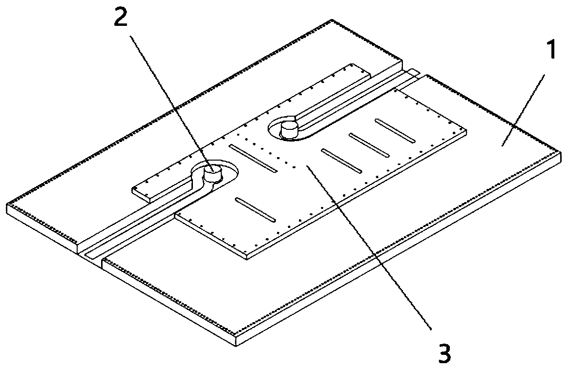
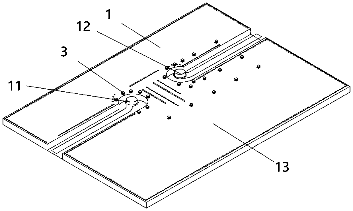
[0045] Such as figure 2 and Figure 6 Shown is the first embodiment of the ceramic filter with CTE compensation according to the present invention, including a filter body 1, and an input end 11 and an output end 12 are provided on the signal transmission surface 13 of the filter body 1 , in order to eliminate the need to connect the PCB board, effectively reduce the cost of use, it can also improve the buffer performance when connecting with the communication system board, and can also retain the ability to support the filter, connect the signal to the ground, and the CTE of the ceramic and the communication system board when using the PCB board Inconsistent compensation function, the ceramic filter with CTE compensation according to the present invention also includes several first elastic metal pads 3 for connecting the communication system board; the first elastic metal pads 3 are discretely arranged on the The signal transmission surface 13 is staggered with the input e...

Embodiment 2

[0051] Figure 7 Shown is the second embodiment of the ceramic filter with CTE compensation according to the present invention, the only difference between it and the first embodiment above is that the cross section of the first elastic sheet structure is bent The arc structure 37 of 36, so that the signal line can be routed from the cutout part of the first shrapnel structure, and the electrical effect is better. However, compared with the first elastic sheet structure with a rectangular structure 35 with a bend 34 in the longitudinal section, the first elastic sheet structure with an arc-shaped structure 37 with a bend 34 in the cross section has slightly poorer elasticity, so the effect of buffering stress is relatively low. Poor, but the installation stability with the communication system board is relatively high. In this embodiment, the arc-shaped structure is a superior arc-shaped structure, and the arc length of the superior arc-shaped structure is 3 / 4 of a circle. Spe...

Embodiment 3

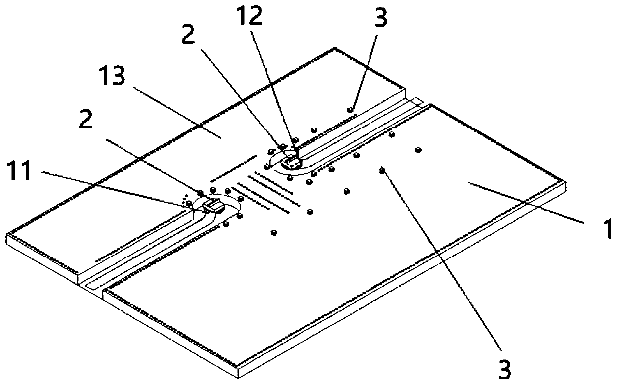
[0053] image 3 Shown is the third embodiment of the ceramic filter with CTE compensation described in the present invention, the only difference between it and the above first embodiment is: the input end 11 and the output end 12 are also provided with The second elastic metal pad 2; the coefficient of thermal expansion of the second elastic metal pad 2 is equivalent to that of the PCB board.

[0054] The input end 11 and output end 12 on the filter body 1 are provided with second elastic metal pads 2 instead of the existing copper pins as the signal transmission end, which is more elastic, so the buffer performance is better when connected to the communication system board.

[0055] As a further improvement of this embodiment, such as Figure 5 As shown, the second elastic metal pad 2 is a second elastic sheet structure. The second elastic sheet structure includes a third welding portion 21 for connecting the input end 11 and the output end 12, a fourth welding portion 22 ...


PUM

PropertyMeasurementUnit
Lengthaaaaaaaaaa
Widthaaaaaaaaaa
Heightaaaaaaaaaa

Abstract

The invention discloses a ceramic filter with CTE compensation. The ceramic filter comprises a filter body. The signal transmission surface of the filter body is provided with an input end and an output end. The ceramic filter is free of a connecting PCB, can effectively reduce use cost, can improve the buffer performance during connection with a communication system board and can reserve the functions of supporting the filter, connecting signals to the ground and compensating CTE inconsistency of the ceramic and the communication system board when the PCB is used; the ceramic filter with CTEcompensation further comprises a plurality of first elastic metal bonding pads used for being connected with the communication system board; the first elastic metal bonding pads are discretely arranged on the signal transmission surface and are staggered with the input end and the output end; and the thermal expansion coefficient of the first elastic metal bonding pad is equivalent to the thermalexpansion coefficient of the PCB.

Description

technical field [0001] The invention relates to the technical field of communication, in particular to a dielectric waveguide filter which can be directly installed on a communication system board and has CTE (that is, coefficient of thermal expansion) compensation. Background technique [0002] With the widespread application of 5G technology, the demand for 5G base stations is gradually increasing, and ceramic dielectric filters have gradually become important components used by various equipment manufacturers. Among them, there are mainly two schemes of single-layer ceramic dielectric filter and double-layer ceramic dielectric filter. [0003] Single-layer ceramic dielectric filters are usually assembled with a supporting PCB board and mounted on the communication system board for use. When used in a single layer, the added PCB board plays the role of supporting the ceramic dielectric filter, connecting the signal ground, and compensating for the CTE inconsistency betwee...

Claims


Application Information

Patent Timeline
IPC IPC(8): H01P1/20H01P1/30
CPCH01P1/2002H01P1/30
Inventor 闵祥会伍隽李荣浩李鹏飞潘彦龙蒋匆聪闫松凌
Owner SHENZHEN SUNLORD ELECTRONICS
Why Eureka
Try Eureka