
Load-reducing suspension system and backpack

A suspension system and component technology, applied in the field of backpacks, can solve the problems of short service life, inability to reduce the load, difficult to adjust, etc., and achieve the effects of stable and reliable sliding space, lightening the burden on the body, and good environmental adaptability

Pending Publication Date: 2020-06-19
南京强钧防务科技研究院有限公司
View PDF1 Cites 2 Cited by
  • Summary
  • Abstract
  • Description
  • Claims
  • Application Information

AI Technical Summary

Problems solved by technology

This results in a short lifespan of the product and is easily damaged
In addition, in its design, the rubber elastic rope can only adapt to the load of a certain weight. If the weight is not enough, the backpack will rise above the back in the free state, making it difficult to slide on the back. If the weight exceeds, the backpack will fall in the free state It is also difficult to slide on the back to the hip, it is difficult to adjust according to the weight of the load, and it cannot achieve a satisfactory load reduction effect for the rated load
[0005] Further, in the prior art, a linear ordinary spring is also used as the elastic body. The ordinary extension spring can generally stretch 50% of the original length of the spring. In order to achieve a better load reduction effect, if only 50% of the original Long, the total length of the back of the human body is about 60 cm, so the maximum length can only be stretched about 20 cm, and the elastic coefficient of the spring is relatively large, which is difficult to meet the effect of suspension and lightening

Method used


Image

  • Load-reducing suspension system and backpack
  • Load-reducing suspension system and backpack
  • Load-reducing suspension system and backpack

Examples


Embodiment 1

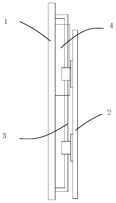
[0039] Such as Figure 1 to Figure 3 As shown, the load-reducing suspension system includes a fixed plate 1 and a sliding plate 2. The sliding plate 2 is connected to the fixed plate 1 through a sliding part 3. It is characterized in that: the fixed plate 1 is provided with an adjustable elastic component 4, which can The movable end of the adjustable elastic component 4 is connected with the sliding plate 2, and the adjustable elastic component can be adjusted according to the load on the sliding plate, so that the force output by the adjustable elastic component just offsets the gravity of the load. When it is on the board, the movable plate will move downward under the action of the load. If the sliding plate slides to the lower limit position of the sliding part, the entire load-reducing suspension system will be in a state of failure and cannot achieve the effect of reducing the load. At this time, this implementation For example, the adjustable elastic component can be a...

Embodiment 2

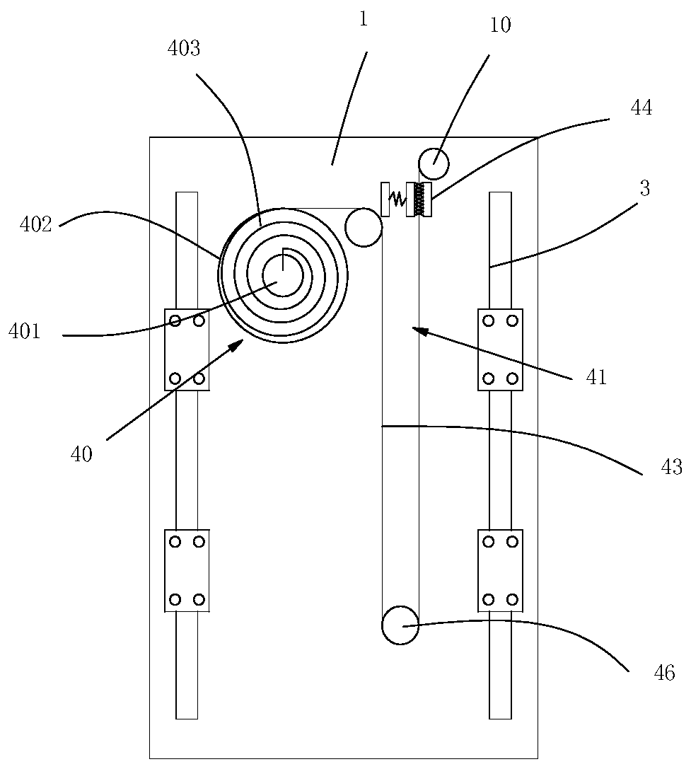
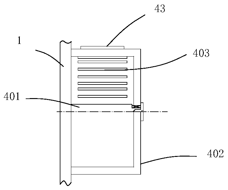
[0044] Such as figure 1 as well as Figure 4 to Figure 6 As shown, the load-reducing suspension system includes a fixed plate 1 and a sliding plate 2. The sliding plate 2 is connected to the fixed plate 1 through a sliding part 3. It is characterized in that: the fixed plate 1 is provided with an adjustable elastic component 4, which can The movable end of the adjustable elastic component 4 is connected with the sliding plate 2, and the adjustable elastic component can be adjusted according to the load on the sliding plate, so that the force output by the adjustable elastic component just offsets the gravity of the load. When it is on the board, the movable plate will move downward under the action of the load. If the sliding plate slides to the lower limit position of the sliding part, the entire load-reducing suspension system will be in a state of failure and cannot achieve the effect of reducing the load. At this time, this implementation For example, the adjustable elast...

Embodiment 3

[0050] Such as figure 1 as well as Figure 7 As shown, the load-reducing suspension system includes a fixed plate 1 and a sliding plate 2. The sliding plate 2 is connected to the fixed plate 1 through a sliding part 3. It is characterized in that: the fixed plate 1 is provided with an adjustable elastic component 4, which can The movable end of the adjustable elastic component 4 is connected with the sliding plate 2, and the adjustable elastic component can be adjusted according to the load on the sliding plate, so that the output force of the adjustable elastic component just offsets the gravity of the load.

[0051] further as Figure 7 As shown, the adjustable elastic assembly 4 includes two symmetrically arranged adjustable torque assemblies 45, and the adjustable torque assembly 45 includes an adjustable mandrel assembly 450 that is installed on a fixed plate to rotate and lock. A rotatable spring box 402 is connected to the mandrel assembly, and a scroll spring 403 wou...


PUM


Abstract

The invention belongs to the field of backpacks, and particularly relates to a load-reducing suspension system capable of remarkably reducing force exerted on a wearer by a load and a backpack with the load-reducing suspension system. The load-reducing suspension system comprises a fixed plate and a sliding plate, wherein the sliding plate is connected to the fixed plate through a sliding part, anadjustable elastic assembly is arranged on the fixed plate, the movable end of the adjustable elastic assembly is connected with the sliding plate, and the adjustable elastic assembly can be adjustedaccording to the load on the sliding plate, so that the force output by the adjustable elastic assembly is just counteracted with the gravity of the load. According to the invention, actual loads aredifferent; the adjustable elastic assembly is adjusted to be matched with the load weight; the adjustable elastic assembly has a good deformable space within the rated load range, then the load reduction effect can be effectively achieved, further, the volute spiral spring is adopted as a torque assembly of the adjustable elastic assembly, and compared with an elastic rope, the adjustable elasticassembly has the longer service life and better environmental adaptability.

Description

technical field [0001] The invention belongs to the field of backpacks, in particular to a load-reducing suspension system which significantly reduces the force of a load acting on a wearer and a backpack with the load-reducing suspension system. Background technique [0002] As a common load transportation method, backpacks are often used in activities such as wilderness survival, military and police duty, emergency rescue, and mountaineering. For an ordinary backpack, when the backpack is stationary, the force exerted by the backpack on the body is only the static force, which is equal to the weight of the backpack. However, when walking or running while wearing a backpack, the peak force exerted on the body can increase significantly to 2-3 times greater than the static force, and this increase in peak force can place very high forces on the joints, causing muscle Injuries and even joint injuries. [0003] Research has shown that peak force is associated with the heave ...

Claims


Application Information

Patent Timeline
Patent Type & Authority Applications(China)
IPC IPC(8): A45C13/00A45F3/04
CPCA45C13/001A45C13/007A45F3/04
Inventor 赵文龙
Owner 南京强钧防务科技研究院有限公司
Learn More