Pipeline scale removal device

A pipeline and heat exchange device technology, applied in the field of pipeline descaling devices, can solve the problems of difficult removal of magnesium ammonium phosphate crystals and high cost, and achieve the effect of low cost and high efficiency removal

Inactive Publication Date: 2020-06-19
河北首朗新能源科技有限公司
View PDF5 Cites 0 Cited by
  • Summary
  • Abstract
  • Description
  • Claims
  • Application Information

AI Technical Summary

Problems solved by technology

[0005] The invention provides a pipeline descaling device, which solves the technical problem of difficult removal of magnesium ammonium phosphate crystals in s...

Method used


Image

  • Pipeline scale removal device

Examples


Embodiment 1

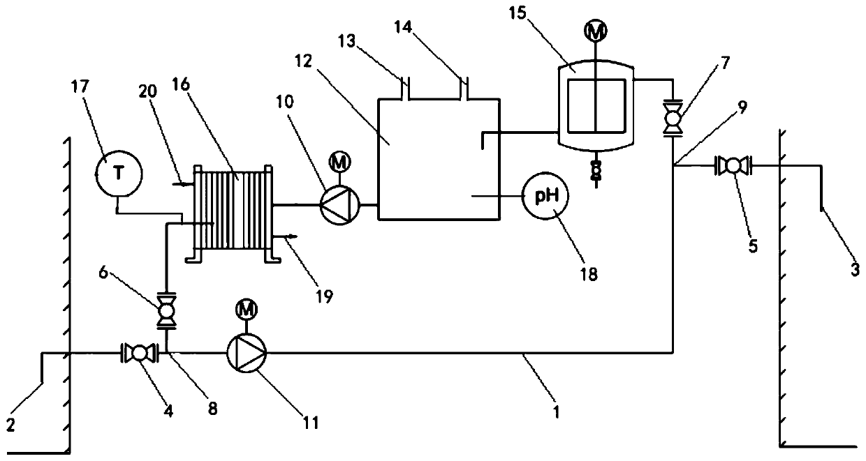
[0026] The embodiment of the present invention provides a pipeline descaling device, please refer to the attached figure 1 , for removing the crystallization of magnesium ammonium phosphate on the first pipeline 1, the first pipeline 1 includes a first inlet 2, a first outlet 3, a first hand valve 4 is arranged at the first inlet 2, a second hand A valve 5 is provided at said first outlet 3 .

[0027] Specifically, the pipeline descaling device is used to remove magnesium ammonium phosphate crystals in the first pipeline 1, the first pipeline 1 is a sewage treatment pipeline, and organic waste water enters the pipeline from the first inlet 2. In the first pipeline 1, the first pipeline 1 is discharged from the first outlet 3. The first hand valve 4 is set at the first inlet 2 for controlling the flow of organic waste water entering the first pipeline 1; the second hand valve 5 is set at the first outlet 3 , used to control the flow of organic wastewater flowing out of the fi...

Embodiment 2

[0080] This application also provides a method of using the pipeline descaling device, please refer to the attached figure 1 , the usage methods include:

[0081] Step 1: Close the first hand valve 4, the second hand valve 5, the third hand valve 6, and the fourth hand valve 7, open the fifth hand valve, and empty the first liquid in pipe 1;

[0082] Specifically, close the third hand valve 6 and the fourth hand valve 7 to prevent the cleaning liquid in the second pipeline from entering the first pipeline 1; close the first hand valve 4 and the The second hand valve 5 is used to prevent the organic wastewater from entering the first pipeline 1. Then, the fifth hand valve is opened, and the liquid in the first pipeline 1 is discharged from the fifth hand valve under the action of gravity.

[0083] Step 2: Open the third hand valve 6, the fourth hand valve 7, the filter 15, the first water pump 10, the second water pump 11, the heat exchange device 16, close the The fifth ha...


PUM


Abstract

The invention discloses a pipeline scale removal device. The pipeline scale removal device is installed on a first pipeline. A first hand valve is arranged in a first inlet, and a second hand valve isarranged in a first outlet. The pipeline scale removal device comprises a second pipeline. The second pipeline comprises a second outlet, a second inlet, a third hand valve, a first water pump, a cleaning fluid buffering tank and a fourth hand valve. The second outlet communicates with the first pipeline and is located behind the first hand valve. The second inlet communicates with the first pipeline and is located in front of the second hand valve. An outlet of the third hand valve communicates with the outlet of the second pipeline. An outlet of the first water pump communicates with an inlet of the third hand valve. An outlet of the cleaning fluid buffering tank communicates with an inlet of the first water pump. The cleaning fluid buffering tank comprises an acid addition opening, a water addition opening and a filter. The acid addition opening is connected with an acid addition device, the water addition opening is connected with a water addition device, and an outlet of the filter communicates with an inlet of the cleaning fluid buffering tank. An inlet of the fourth hand valve communicates with the second inlet, and an outlet of the fourth hand valve communicates with an inlet of the filter. The technical effects that the pipelines do not need to be replaced, magnesium ammonium phosphate crystals in the sewage treatment pipelines are efficiently removed, and the cost islow are achieved.

Description

technical field [0001] The invention relates to the technical field of sewage treatment, in particular to a pipeline descaling device. Background technique [0002] In the water treatment industry, anaerobic treatment has been widely used as a treatment technology with low energy consumption and high efficiency. After anaerobic treatment, organic wastewater still contains some ammonium ions, magnesium ions and phosphate ions. If the three When the concentration product of ions exceeds the solubility product formed by magnesium ammonium phosphate, insoluble crystal MgNH4PO4·6H2O (MAP, magnesium ammonium phosphate) will be formed. Magnesium ammonium phosphate scaling is easy to appear in places with turbulent water flow such as inlet and outlet pipes, sludge return pipes, and pump impellers. Especially after anaerobic treatment is completed, the anaerobic effluent is transferred to aerobic treatment, causing pipeline blockage and reducing The efficiency of pipeline transporta...

Claims


Application Information

Patent Timeline
IPC IPC(8): B08B9/032B08B13/00
CPCB08B9/0321B08B13/00
Inventor 宋庆坤希宗坡王晓东莫志朋夏楠王兴凯宗福宝雷旭
Owner 河北首朗新能源科技有限公司
Why Eureka
Try Eureka