
Eureka
For R&D, Eureka makes reading and utilizing patents & technical documents easy.
Eureka AIR
Designed for self-driven R&D workflows. Generate viable solutions, solve complex R&D challenges, empower your innovation with AI.

Eureka Materials
Designed for material experts only. Revolutionize your material R&D, from search, analyze, to developing new materials.

TechResearch
Generate reliable direction feasibility study reports for your R&D in just a few steps.

TechSeek
Discover and master advanced knowledge NOW. Basics, ideas, possibilities, all at once.

TechMind
As an expert in R&D Theories, TechMind can generates customized viable solutions instantly.

TechRisk
Analyze your overall solution with one click, know your potential R&D risks in advance.

TechMonitor
Get weekly tech updates, stay abreast of the latest tech innovations and key insights.
Large-diameter hot billet cutting-off device
A technology of cutting device and cutting mechanism, which is applied in the field of shaft blank cutting, can solve the problems of poor flatness of cutting section, frequent tool replacement, large tool loss, etc., achieve good work efficiency, good cutting stability, and reduce workload Effect
- Summary
- Abstract
- Description
- Claims
- Application Information
AI Technical Summary
Problems solved by technology
Method used
Image

Examples
Embodiment 1
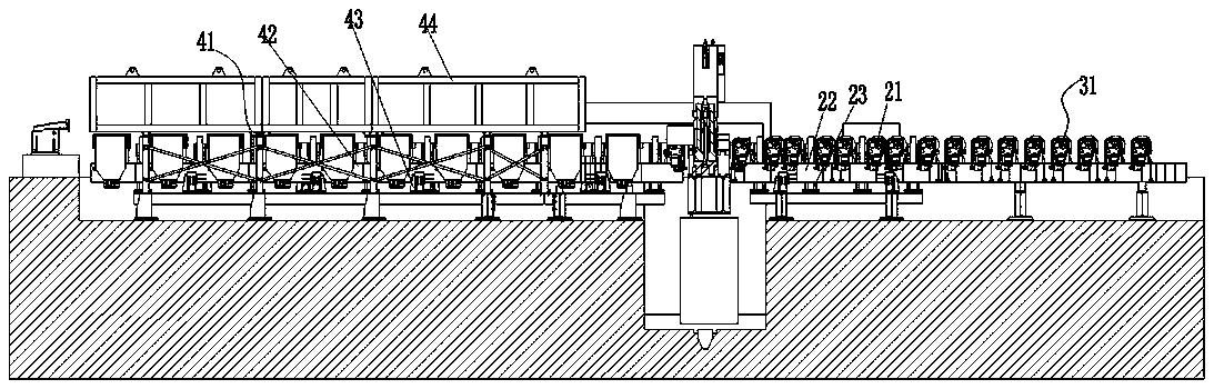
[0041] Embodiment 1: as Figure 1-2 As shown, a large-diameter hot billet cutting device is used in conjunction with a continuous casting machine, including a frame, which can be formed by connecting various profiles. No specific introduction is made here. The frame is sequentially provided with Conveying area, lifting and conveying follow-up area, cutting area, lifting and conveying follow-up heat preservation area; the conveying area is provided with a first conveying roller 31;
[0042] The lifting and conveying follow-up area is provided with a second conveying roller 21, a first stick frame 22 for installing the second conveying roller 21, and a first lifting device 23 for driving the first stick frame 22 to lift ;
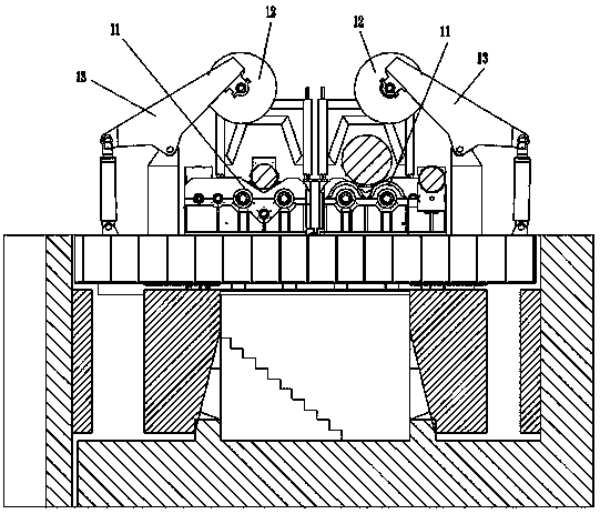
[0043]The cutting area is provided with a cutting mechanism; the cutting mechanism includes a bearing roller 11 for carrying the hot billet, a driving mechanism for driving the hot billet and making the hot billet rotate with the central axis of the hot bill...
Embodiment 2
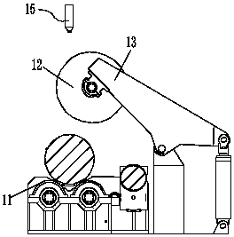
[0050] Embodiment 2: different from embodiment 1, such as Figure 4 As shown, the cutting mechanism also includes a radial pressure roller 14 correspondingly arranged relative to the pressure knife 12, which is used to level the bulge caused by extrusion at the pressed part of the hot billet, and is arranged above the bearing roller 11, which can be Symmetrical distribution on both sides of the hot billet, attached Figure 4 It only shows that the radial pressure roller 14 is set on one side, and does not indicate that the radial pressure roller 14 is set on both sides, so as to prevent the hot billet from being greatly bulged due to axial extrusion and deform the radial bulge of the hot billet. Keep it within an acceptable range, reduce the workload of the subsequent finishing of the short blank after cutting, and at the same time, due to the existence of the radial pressure roller 14, when the pressure knife 12 exerts a pressure facing the radial pressure roller 14, the diam...
Embodiment 3
[0052] Embodiment 3: Different from Embodiment 1, the roller surface of the carrying roller 11 is a supporting leveling plane capable of leveling the bulging portion of the hot billet at the pressure-receiving position due to extrusion. With this arrangement, since the bearing roller 11 plays two roles of supporting and leveling, there is no need to set up additional leveling components such as pressing rollers to level the bulging part of the hot billet pressure part due to extrusion, so that the entire cutting Mechanism, less parts consumption, simple structure and low cost.
[0053] Further, such as Image 6 As shown, the roller surface of the carrying roller 11 is provided with a second annular material avoidance opening 111 facing the press knife 12 .
PUM
 Abstract
Description
Claims
Application Information
 - R&D Engineer
- R&D Manager
- IP Professional
- Industry Leading Data Capabilities
- Powerful AI technology
- Patent DNA Extraction
Browse by: Latest US Patents, China's latest patents, Technical Efficacy Thesaurus, Application Domain, Technology Topic, Popular Technical Reports.
© 2024 PatSnap. All rights reserved.Legal|Privacy policy|Modern Slavery Act Transparency Statement|Sitemap|About US| Contact US: help@patsnap.com