Construction method for canal penetration drainage of underground utility pipe gallery

A technology of integrated pipe gallery and construction method, applied in artificial islands, water conservancy projects, underwater structures, etc., can solve problems such as delay in construction period, difficult coordination, and project shutdown, and achieve increased safety and reliability, overall stable operation, The effect of strong bearing capacity

Inactive Publication Date: 2020-06-19
CHINA FIRST METALLURGICAL GROUP
View PDF2 Cites 3 Cited by
  • Summary
  • Abstract
  • Description
  • Claims
  • Application Information

AI Technical Summary

Problems solved by technology

Practice has proved that on-site plane coordination is required before diversion construction, which will involve land acquisition, demolition, and relocation of towers, building structures, ponds and other factors along the diversion canal, which will greatly occupy the construction period and even cause the project to stop. The construction period is delayed, or when the coordination is not feasible, the original design plan is adjusted, etc.
At the same time, there are problems in the construction of drainage canals such as long length, high cost, low construction efficiency, and poor stability, and most of the drainage canal and cofferdam materials are not suitable for turnover, which is a huge waste
[0004] The present invention intends to design a construction method for drainage through rivers and canals by underground comprehensive pipe gallery, which can effectively solve the difficulties in coordination, low construction efficiency, long construction period, poor safety and stability, and high cost of drainage in common rivers and canals when the water flow is large. Due to practical problems such as low material recovery rate, the upper part of the pipe gallery foundation pit is erected to support the Bailey frame and the water pipe to divert the river from the upstream to the downstream

Method used


Image

  • Construction method for canal penetration drainage of underground utility pipe gallery
  • Construction method for canal penetration drainage of underground utility pipe gallery
  • Construction method for canal penetration drainage of underground utility pipe gallery

Examples


Embodiment Construction

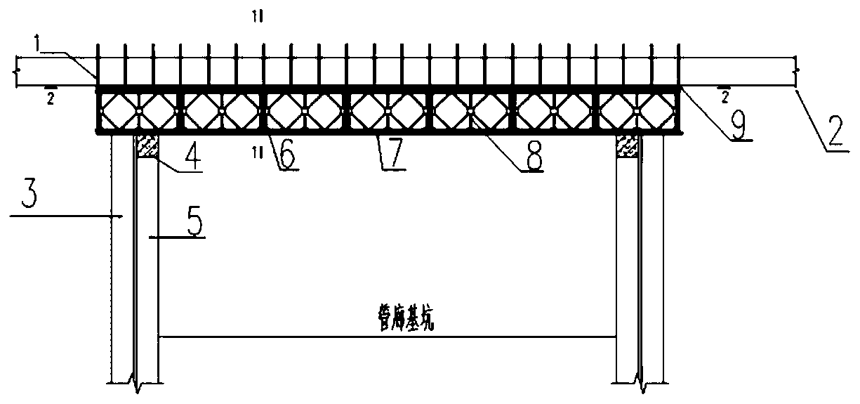
[0030] Below by embodiment, in conjunction with accompanying drawing, the technical scheme of the present invention is described further specifically, as Figure 1-6 As shown, a construction method for drainage of underground comprehensive pipe gallery through river channels, including the following steps:

[0031] Step 1. Foundation pit support: In order to ensure the water blocking effect of the foundation pit of the canal and the requirements for the bearing capacity of the later Bailey frame support, the type of foundation pit support is to set a number of cast-in-place piles 5 from the inside to the outside on both sides of the pipe gallery foundation pit, and the cast-in-place piles 5 wrapping the high-pressure rotary grouting pile 3, pouring the crown beam 4 on the top of the cast-in-place pile 5;

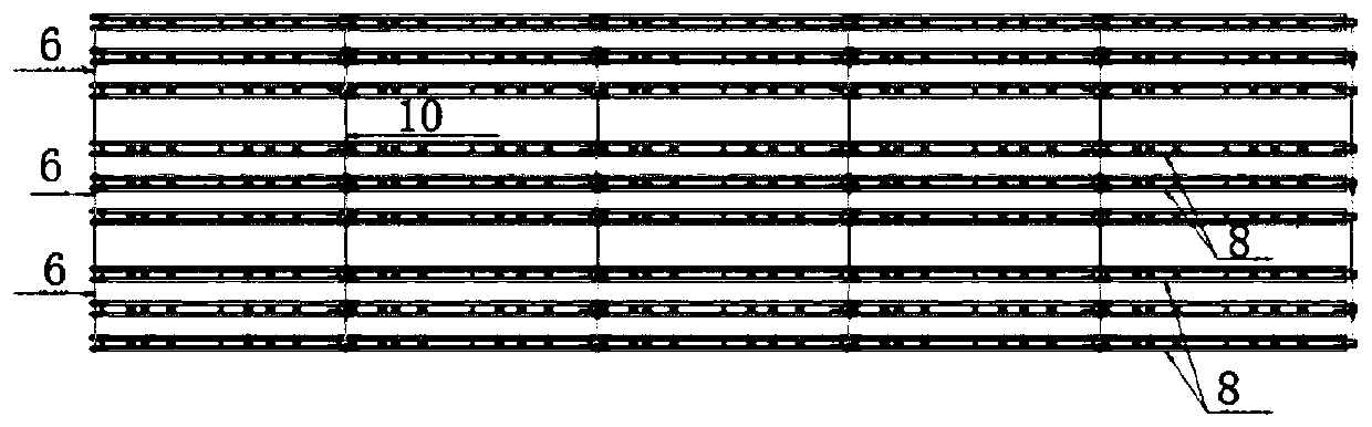
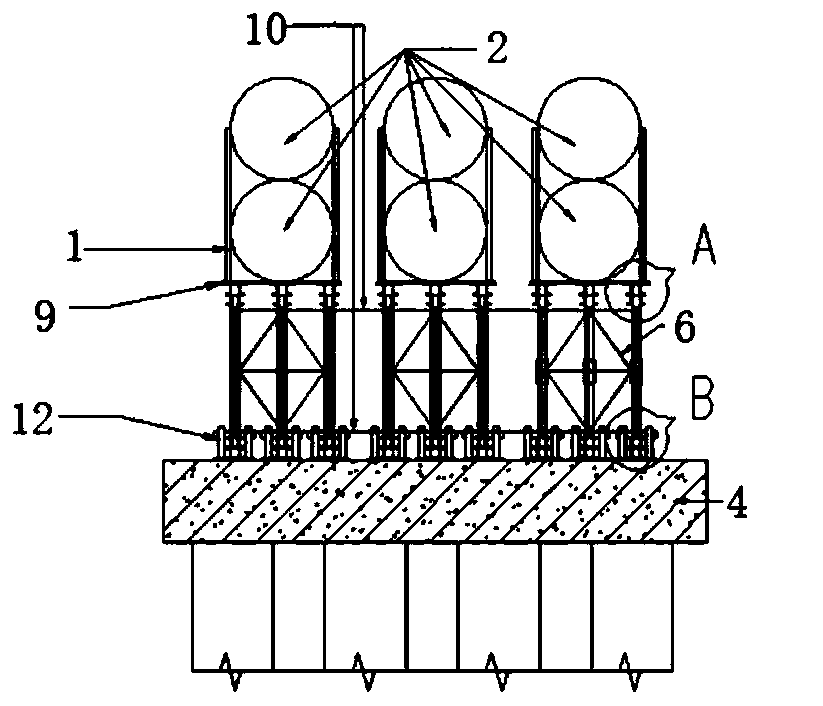
[0032] Step 2. Construction of steel conduit 2 and Bailey frame support system: Build water-passing steel conduit 2 and Bailey frame support at the parallel position where t...


PUM


Abstract

The invention provides a construction method for canal penetration drainage of an underground utility pipe gallery. The construction method is characterized by comprising the following steps of S1, carrying out foundation pit supporting, specifically, arranging a plurality of pouring piles on two sides of a pipe gallery foundation pit from inside to outside, externally coating each pouring pile with a high-pressure jet grouting pile, and pouring a crown beam to the top of each pouring pile; S2, carrying out steel guide pipe and Bailey truss supporting system construction, specifically, constructing a water passing steel guide pipe and a Bailey truss support on parallel positions on an original canal passing position of the foundation pit; and S3, carrying out canal channel flow guide, specifically, extending and constructing a flow guide canal from two ends of the water passing steel guide pipe, favorably making a drainage butt joint and water prevention measure of the flow guide canaland the water passing steel guide pipe, then, after a water passing steel guide pipe and flow guide canal water injection experiment is qualified, draining an original canal to the flow guide canal and the water passing steel guide pipe, and then, blocking the two ends of the original canal so as to realize the safe flow guidance of the canal. A drainage steel pipe of the invention is supported by a Bailey truss, carrying capacity is high, a plurality of pipelines can be carried to simultaneously realize water passing, a drainage device is integrally stable to operate, and a good constructionenvironment is provided for lower pipe gallery construction.

Description

technical field [0001] The invention belongs to the technical field of underground comprehensive pipe gallery, and in particular relates to a construction method for underground comprehensive pipe gallery to pass through rivers and canals for drainage. Background technique [0002] With the continuous advancement of the urbanization process, the application of underground comprehensive pipe corridors in urban municipal construction is more and more favored by urban planners and designers. However, the underground comprehensive pipe gallery involves a large area, and often encounters engineering environments such as crossing existing roads, pipelines, and canals. Among them, the excavation of the foundation pit of the canal pipe gallery is a common construction problem in construction, especially when the water volume of the canal is large and the canal is wide, the difficulty of diversion construction is further increased. [0003] The existing conventional method to solve ...

Claims


Application Information

Patent Timeline
Patent Type & Authority Applications(China)
IPC IPC(8): E02D29/045E02B1/00
CPCE02D29/10E02B1/00
Inventor 郭志国刘凯张桂军白尧尧车二平
Owner CHINA FIRST METALLURGICAL GROUP
Why Eureka
Try Eureka