A layered physical manufacturing device with a fast separation of a computer motherboard melting film

A computer motherboard, layered entity technology, applied in the direction of lamination devices, computing, manufacturing tools, etc., can solve the problems of large processing gap, affecting molding efficiency and quality, and low table movement speed.

Active Publication Date: 2021-05-04
北京神州数码云科信息技术有限公司
View PDF7 Cites 0 Cited by
  • Summary
  • Abstract
  • Description
  • Claims
  • Application Information

AI Technical Summary

Problems solved by technology

[0003] 1. When the computer motherboard is manufactured in solid form, the motherboard sheet is manually placed on the surface of the workbench, which is time-consuming and laborious. The motherboard sheet before and after molding is docked on the corresponding position of the workbench surface by manpower, and it cannot be quickly placed. The main board sheet is placed in the corresponding position in advance, and the other one is formed quickly after one main board sheet is formed, and the processing gap is relatively large, which in turn affects the manufacturing efficiency of the computer main board;
[0004] 2. When manually placing the motherboard sheet, it is impossible to accurately place the motherboard sheet at the corresponding position on the workbench, causing the physical molding to deviate from the original position. At the same time, the motherboard sheet is easy to deviate from the original position during the molding process, which affects the computer motherboard. molding quality and efficiency;
[0005] 3. When forming computer motherboards, the workbench used to hold the molded parts needs to be lifted frequently. In the forming equipment, the workbench bears a large weight, the drive reduction ratio is large, and the movement speed of the workbench is very low. Molded parts cannot be separated quickly, and the material belt is easy to wrinkle due to pulling when detached, which affects the efficiency and quality of molding

Method used


Image

  • A layered physical manufacturing device with a fast separation of a computer motherboard melting film
  • A layered physical manufacturing device with a fast separation of a computer motherboard melting film
  • A layered physical manufacturing device with a fast separation of a computer motherboard melting film

Examples


Embodiment Construction

[0024] The following will clearly and completely describe the technical solutions in the embodiments of the present invention with reference to the accompanying drawings in the embodiments of the present invention. Obviously, the described embodiments are only some, not all, embodiments of the present invention. Based on the embodiments of the present invention, all other embodiments obtained by persons of ordinary skill in the art without making creative efforts belong to the protection scope of the present invention.

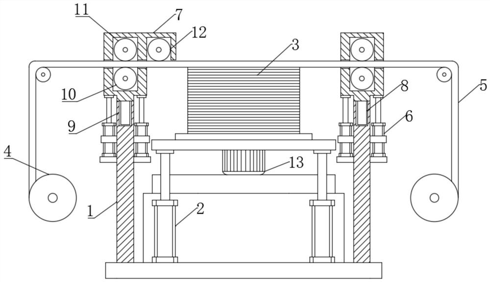
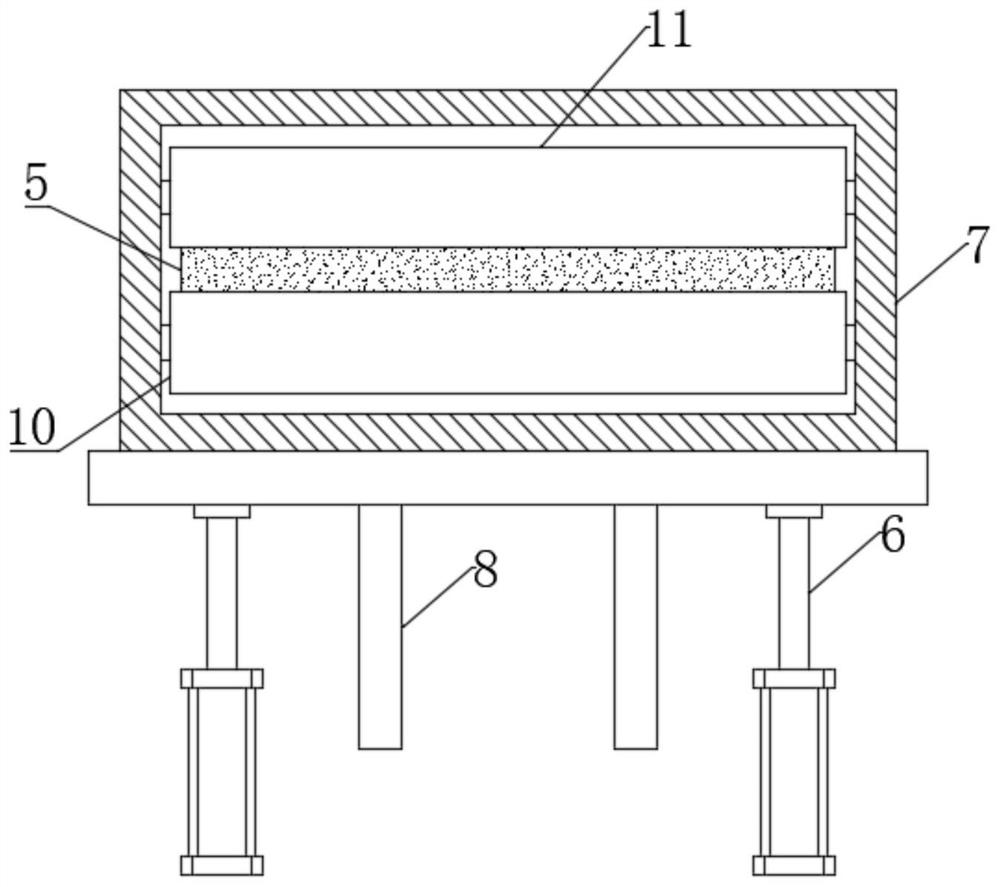
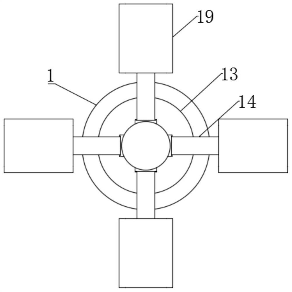
[0025] see Figure 1 to Figure 5 , the present invention provides a technical solution: a layered entity manufacturing device for rapid separation of computer motherboard melt film, including a mounting base 1, the surface of the mounting base 1 is screwed with a first cylinder 2, and the surface of the first cylinder 2 is screwed A workbench 3 is connected, and a feeding roller 4 is provided at the side end of the mounting seat 1, and a material tape 5 is wou...


PUM


Abstract

The invention relates to the related technical field of layered entity manufacturing, in particular to a layered entity manufacturing device for rapid separation of computer motherboard melt film, including a mounting seat, the surface of the mounting seat is screwed with a first cylinder, and the surface of the first cylinder is screwed. It is connected with a workbench, the surface of the connecting seat is welded with a clamping frame, the inner wall of the workbench is screwed with a fourth cylinder, the clamping plate and the positioning splint are both squeezed on the surface of the computer motherboard, and the surface of the positioning splint is sleeved with a spring. The beneficial effect is: after the molding of a computer motherboard is completed, the second cylinder and the first cylinder are respectively adjusted upward and downward, so that the material belt moves upward and the formed computer motherboard moves downward, so that the fast connection between the material belt and the computer motherboard is realized. Detachment improves the molding efficiency, and at the same time, when the material belt rises, the guide roller and the nip roller squeeze the material belt to avoid the wrinkle of the material belt, thereby ensuring the quality of the secondary processing, suitable for promotion.

Description

technical field [0001] The invention relates to the related technical field of layered entity manufacturing, in particular to a layered entity manufacturing device for rapid separation of computer motherboard melt adhesive films. Background technique [0002] Layered solid molding is also called lamination preparation technology in a narrow sense. This technology uses thin sheet materials, lasers, and hot-melt adhesives to make laminated structures. The system mainly includes computers, numerical control systems, raw material storage and transportation components, thermal bonding Parts, laser cutting system, liftable workbench, etc., the laser cutter will cut the film along the cross-sectional contour of the workpiece, and the thermal bonding parts will bond the films in the forming area layer by layer until the workpiece is fully formed. However, the layered entity manufacturing device still has the following disadvantages when manufacturing computer motherboards: [0003]...

Claims


Application Information

Patent Timeline
Patent Type & Authority Patents(China)
IPC IPC(8): G06F1/18B32B37/12B32B37/10B32B37/06B32B37/00B32B38/18B23K26/38
CPCB23K26/38B32B37/0046B32B37/06B32B37/10B32B37/12B32B38/1808B32B38/1825B23K2101/36G06F1/184
Inventor 王成科
Owner 北京神州数码云科信息技术有限公司
Why Eureka
Try Eureka