
Implantable medical device shell structure and implantable medical device

A technology for implanting medical devices and medical devices, used in implanted stimulators, therapy, electrotherapy, etc., can solve the problems of low resistivity, low charging efficiency, strong electromagnetic energy shielding effect, etc., achieve high resistivity, improve charging Efficiency, effect of improving charging efficiency and communication sensitivity

Pending Publication Date: 2020-06-23
TSINGHUA UNIV +1
View PDF0 Cites 0 Cited by
  • Summary
  • Abstract
  • Description
  • Claims
  • Application Information

AI Technical Summary

Problems solved by technology

[0005] Therefore, the technical problem to be solved by the present invention is to overcome the problem that the shell structure of the implantable medical device in the prior art is made of TA1 material, and the resistivity is low. When the medical device implanted into the human body is charged, the resistivity is low. The TA1 material shell has a strong shielding effect on electromagnetic energy, resulting in a technical defect of low charging efficiency, thus providing an implantable medical device shell structure that can improve charging efficiency

Method used


Image

  • Implantable medical device shell structure and implantable medical device
  • Implantable medical device shell structure and implantable medical device
  • Implantable medical device shell structure and implantable medical device

Examples


Embodiment 1

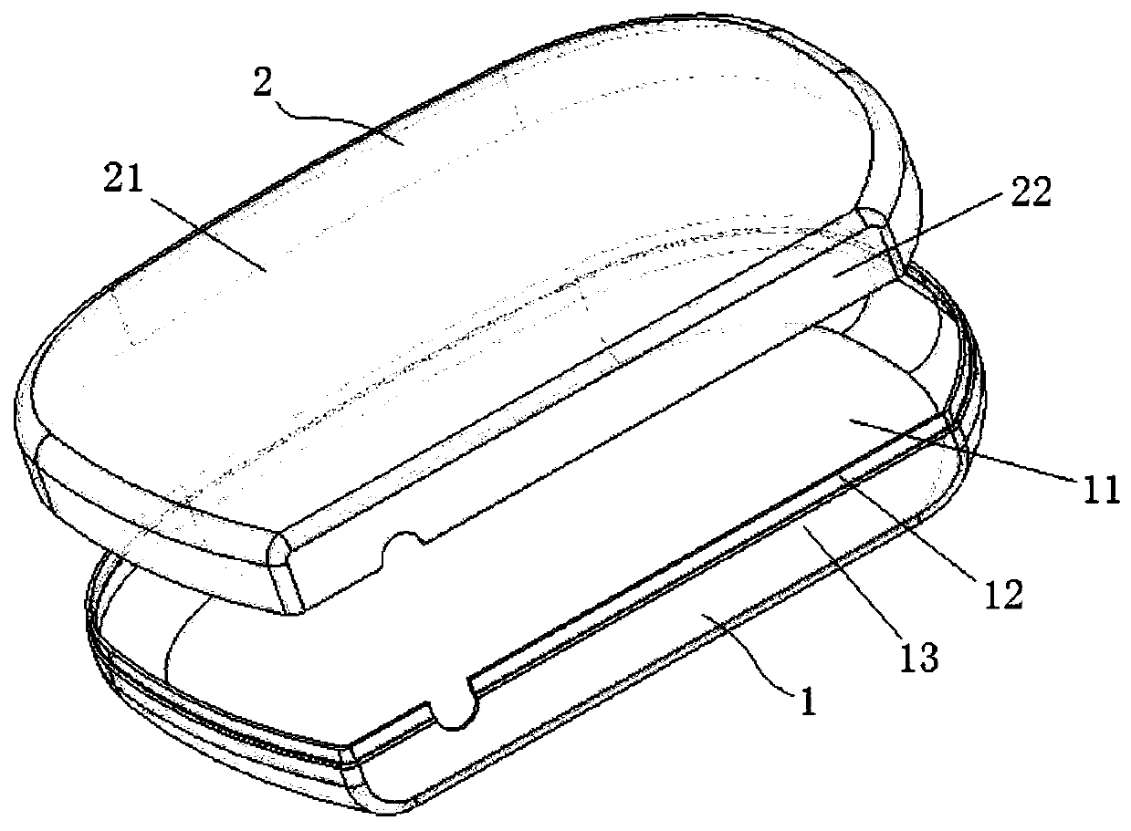
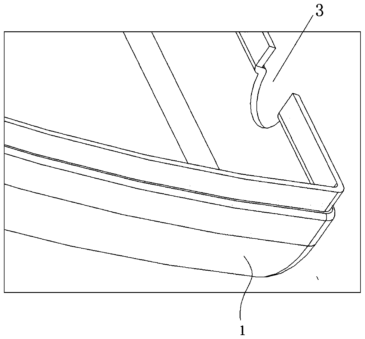
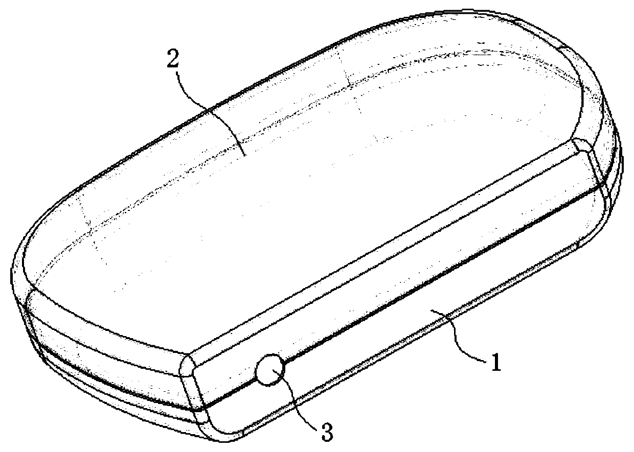
[0037] This embodiment provides an implantable medical device housing structure, such as Figure 1-3 As shown, it includes: a first shell 1 made of a first material; a second shell 2 made of a second material and fixedly connected with the first shell 1 to form a closed or semi-closed shell; Both the first material and the second material are biocompatible materials, and the resistivity of the first material is smaller than that of the second material.

[0038] Specifically, in this embodiment, the first material is TA1 material, and the second material is TC4 material. The second material can also be TC20 material, TA18 or TC4ELI.

[0039] In the housing structure of this embodiment, after the medical device is placed inside the human body, the side of the second housing with a high resistivity faces outward, so that when the external charging device is used to charge the medical device placed inside the housing (refer to Figure 4 shown), the outward-facing second shell 2 ...

Embodiment 2

[0047] This embodiment provides an implantable medical device, which includes a medical device body and a housing for accommodating the medical device body, and the housing is the housing structure described in Embodiment 1.

[0048] The medical device body includes a coil (not shown in the figure) for wireless charging, and the medical device body is arranged such that the coil is located closer to the outwardly facing second housing of the housing structure.


PUM


Abstract

The invention provides an implantable medical device shell structure and an implantable medical device. The shell structure at least comprises a first shell made of a first material and a second shellmade of a second material and fixedly connected with the first shell to form a closed or semi-closed shell, wherein the first material and the second material are both materials capable of meeting biocompatibility, and the resistivity of the first material is smaller than that of the second material. According to the shell structure, after the medical device is placed and implanted into the humanbody, the charging efficiency is high when the medical device placed in the shell is charged through in-vitro charging equipment; and when in-vitro operation equipment is used for communicating withthe in-vivo medical device, the communication sensitivity is high.

Description

technical field [0001] The invention relates to the technical field of implantable medical device shells, in particular to an implantable medical device shell structure and an implantable medical device that need to be charged or communicate with external equipment. Background technique [0002] Implantable medical devices, as the name suggests, are medical devices that can be implanted into the human body. Neurostimulator belongs to one of them, and its treatment principle is to stimulate the target nerve with a certain degree of electric current pulse to adjust or restore the function of brain, nerve or muscle, and relieve symptoms. [0003] The shell of neurostimulators is generally made of TA1 titanium, because TA1 titanium can not only meet the requirements of biocompatibility, but also has good molding ability, and the cost of making various complex structural parts is low. However, with the use and popularization of SCS stimulators (spinal cord stimulators) required ...

Claims


Application Information

Patent Timeline
Patent Type & Authority Applications(China)
IPC IPC(8): A61N1/375A61N1/372A61N1/378A61N1/36
CPCA61N1/375A61N1/3758A61N1/37211A61N1/3787A61N1/3605
Inventor 文雄伟夏泓玮余伟刘方军李路明
Owner TSINGHUA UNIV
Learn More