
Eureka
For R&D, Eureka makes reading and utilizing patents & technical documents easy.
Eureka AIR
Designed for self-driven R&D workflows. Generate viable solutions, solve complex R&D challenges, empower your innovation with AI.

Eureka Materials
Designed for material experts only. Revolutionize your material R&D, from search, analyze, to developing new materials.

TechResearch
Generate reliable direction feasibility study reports for your R&D in just a few steps.

TechSeek
Discover and master advanced knowledge NOW. Basics, ideas, possibilities, all at once.

TechMind
As an expert in R&D Theories, TechMind can generates customized viable solutions instantly.

TechRisk
Analyze your overall solution with one click, know your potential R&D risks in advance.

TechMonitor
Get weekly tech updates, stay abreast of the latest tech innovations and key insights.
Heat exchanger having corrugated fins and air conditioner having the same
A technology of heat exchangers and fins, which is applied in the field of air conditioners, can solve the problems of ozone layer destruction, low heat exchange efficiency, and inability to establish air turbulence, and achieve the effect of low resistance
- Summary
- Abstract
- Description
- Claims
- Application Information
AI Technical Summary
Problems solved by technology
Method used
Image

Examples
Embodiment Construction
[0049] Referring now to the accompanying drawings, preferred embodiments of the present invention will be described.
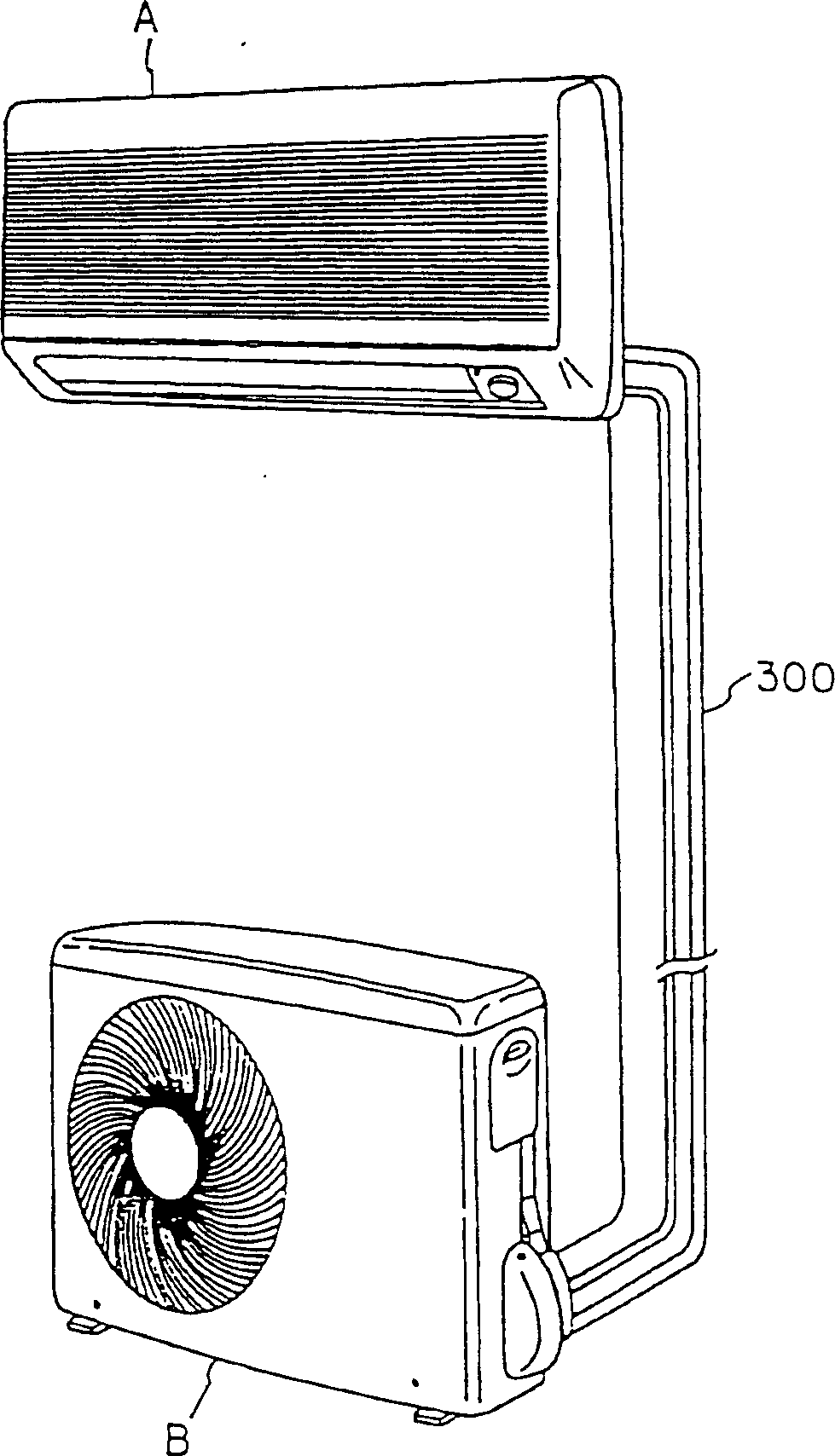
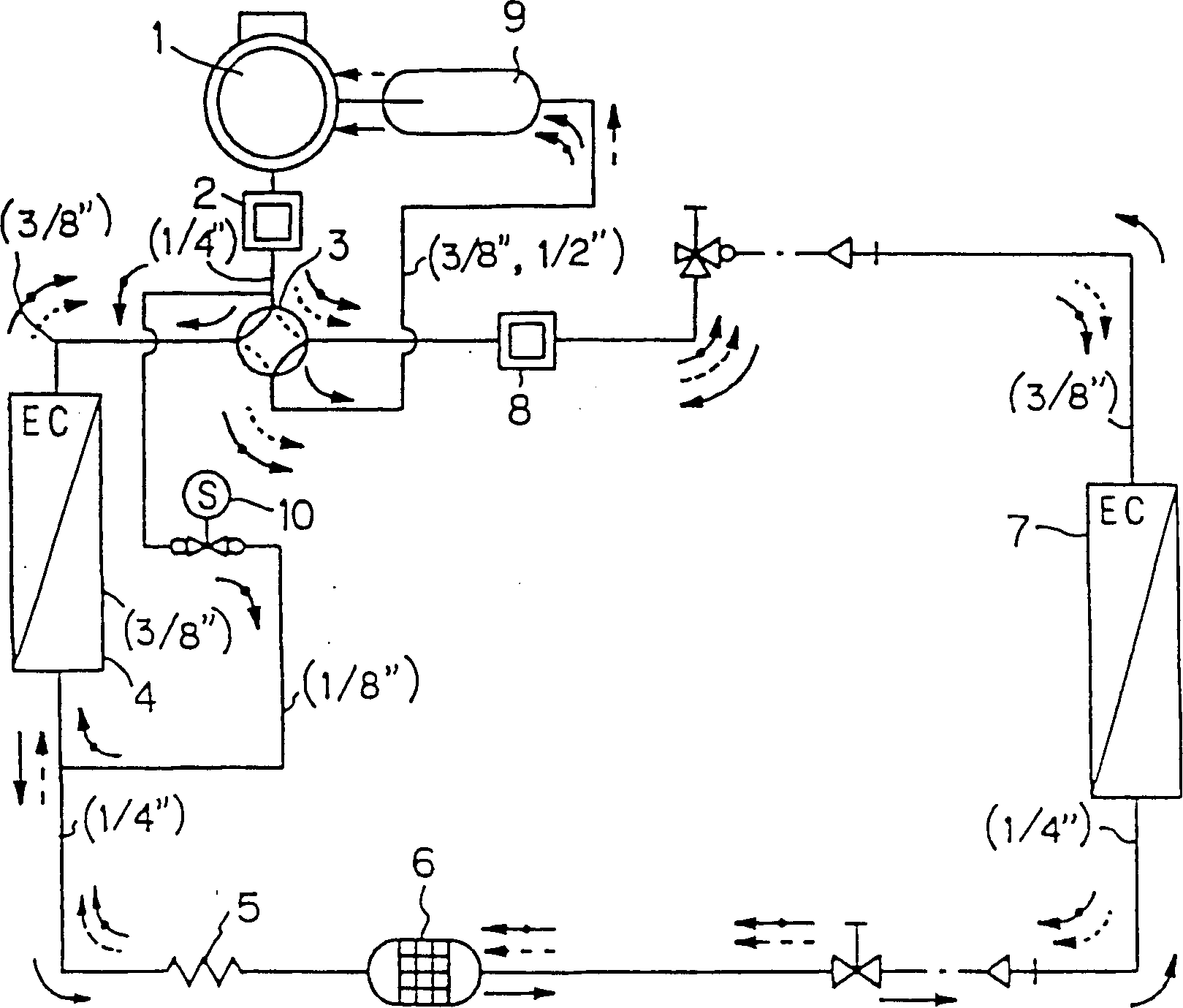
[0050] figure 1 It is a perspective view of a common household air conditioner. This type of air conditioner has a user side unit A (indoor unit) installed indoors and a heat source side unit B (outdoor unit) installed outdoors, and the indoor unit A and the outdoor unit B communicate with each other through a refrigerant pipe 300 . figure 2 yes means figure 1 A schematic diagram of the refrigerant circuit of the refrigeration circuit of the air conditioner shown.
[0051] Such as figure 2 As shown, the refrigerant circuit includes a compressor 1 composed of a motor part and a motor-driven compression part; a muffler for suppressing the vibration and noise caused by the intermittent discharge of the refrigerant from the compressor 1; switching the refrigerant between Four-way switching valve for flow direction during cooling / heating operation 3; heat exc...
PUM
 Abstract
Description
Claims
Application Information
 - R&D Engineer
- R&D Manager
- IP Professional
- Industry Leading Data Capabilities
- Powerful AI technology
- Patent DNA Extraction
Browse by: Latest US Patents, China's latest patents, Technical Efficacy Thesaurus, Application Domain, Technology Topic, Popular Technical Reports.
© 2024 PatSnap. All rights reserved.Legal|Privacy policy|Modern Slavery Act Transparency Statement|Sitemap|About US| Contact US: help@patsnap.com