
Water production gas well full-life-circle drainage gas recovery method and system

A full-life-cycle, drainage and gas production technology, applied in the fields of fluid production, earthwork drilling, wellbore/well components, etc., can solve problems such as difficulty in meeting drainage and gas production requirements of gas wells, affecting gas well production effects, and increasing operating costs, etc. Achieve the effect of avoiding generator efficiency loss, avoiding line short-circuit fault, and avoiding compression efficiency loss

Active Publication Date: 2020-06-23
西安诚科石油工程技术服务有限公司
View PDF13 Cites 9 Cited by
  • Summary
  • Abstract
  • Description
  • Claims
  • Application Information

AI Technical Summary

Problems solved by technology

In the case of low gas output in the later stage, considering the energy consumption and output ratio, generally the compressor will not continue to be used for drainage and gas recovery, resulting in a waste of gas well resources
[0005] In addition, the above-mentioned drainage and gas recovery methods currently used are all single-use, and their application range is greatly limited, and it is difficult to meet the drainage and gas recovery needs of the entire life cycle of the gas well; not only the overall operating cost increases, but also affects the gas well production effect

Method used


Image

  • Water production gas well full-life-circle drainage gas recovery method and system
  • Water production gas well full-life-circle drainage gas recovery method and system
  • Water production gas well full-life-circle drainage gas recovery method and system

Examples


Embodiment Construction

[0040] In order to make the purpose, technical solution and advantages of the application clearer, the embodiments of the application will be described in detail below in conjunction with the accompanying drawings. It should be noted that, in the case of no conflict, the embodiments in the present application and the features in the embodiments can be combined arbitrarily with each other.

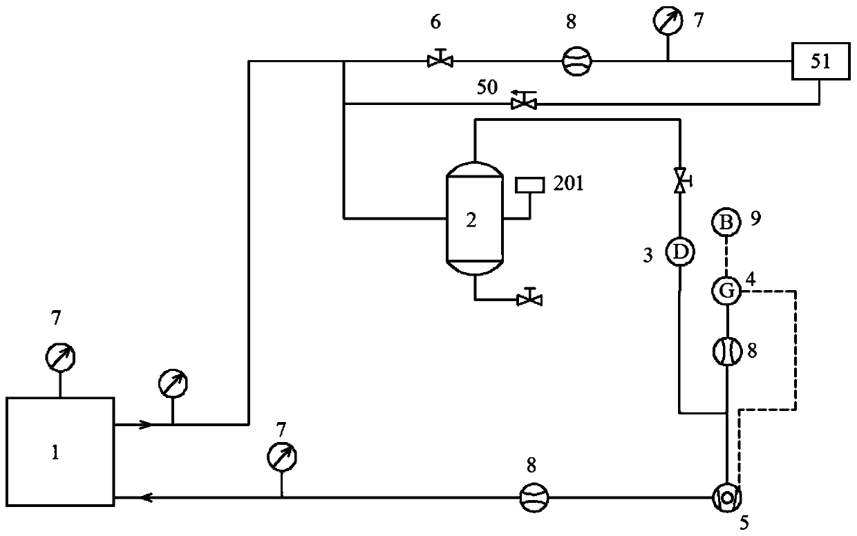
[0041] Such as figure 1 , which shows a schematic diagram of the overall layout of a water-producing gas well life-cycle drainage and gas recovery system of the present application. As shown in the figure, the drainage gas collection system includes drainage gas collection equipment 1 , gas-water separation device 2 , drying equipment 3 , gas generator 4 , and compressor 5 . The outlet pipeline of the drainage and gas production equipment 1 is divided into two branches, the first branch is connected with a regulating valve 6, a flow regulator 8 and a barometer 7, and is finally connected t...


PUM


Abstract

The invention relates to a water production gas well full-life-circle drainage gas recovery method and system. The system comprises drainage gas recovery equipment, a gas-water shunting device, dryingequipment, a gas power generator and a compressor. A first branch of an outlet pipeline of the drainage gas recovery equipment is connected to an outer conveying pipe network. A second branch is connected with the gas-water shunting device. Gas flowing out of the top of the gas-water shunting device passes through an adjusting valve and is dried through the drying equipment, then the gas is divided into two branches, one branch flows into the gas power generator through a flow adjuster, the other branch flows into the compressor, and the gas power generator provides electric energy for the compressor by burning natural gas. The natural gas is pressurized through the compressor, multiple stages of pressure adjusters are started by the natural gas, shaft accumulated liquid is removed section by section, and continuous production of a gas well is guaranteed. The method and system can be suitable for water production gas well full-life-circle drainage gas recovery, one-time construction is effective for a long time, the gas lift starting pressure is low, the energy consumption is low, external electric energy does not need to be used, and the method and system are safe, reliable, capable of being reused, easy to manage and low in maintenance cost.

Description

technical field [0001] The application relates to a water-producing gas well life-cycle water drainage and gas recovery method and system, which is applicable to the technical field of gas well drainage and gas recovery. Background technique [0002] During the production of natural gas wells, we often encounter the phenomenon of bottom-hole fluid accumulation. If these fluid accumulations cannot be discharged out of the well in time, it will not only have a great impact on the production of the gas well, but also affect the ultimate recovery of the gas well. Therefore, certain drainage measures must be adopted, and every effort must be made to eliminate the bottom fluid. The liquid in the gas well is mainly gaseous hydrocarbon condensate and formation water, which are distributed in the gas phase in the form of liquid droplets, and the liquid is usually sent to the surface in the form of liquid droplets under the action of the gas phase. If the gas phase cannot provide an ...

Claims


Application Information

Patent Timeline
Patent Type & Authority Applications(China)
IPC IPC(8): E21B43/16E21B43/34
CPCE21B43/16E21B43/34
Inventor 李跃刚崔斌上官丰收韩少帅路文强
Owner 西安诚科石油工程技术服务有限公司
Learn More