

Ultrahigh-frequency X-ray flaw detector
An X-ray and flaw detector technology, which is used in material analysis, measuring devices, and instruments using wave/particle radiation. The effect of satisfying the conditions of safe use and simple structure
- Summary
- Abstract
- Description
- Claims
- Application Information
AI Technical Summary
Problems solved by technology
Method used
Image

Examples
Embodiment 1
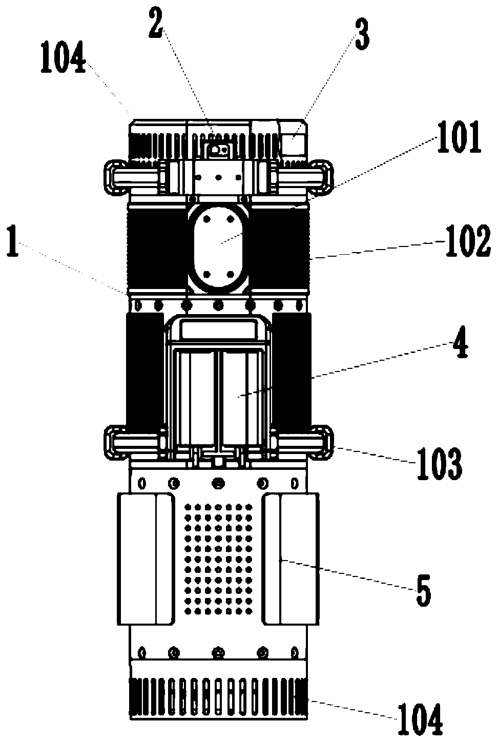
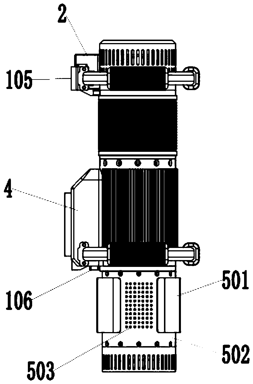
[0037] Such as Figure 1-3As shown, an ultra-high frequency X-ray flaw detection machine and a control system include a casing 1, one end of the casing 1 is provided with a first cooling fan 3, and the first cooling fan 3 adopts a blowing method to dissipate heat, and the other end of the casing 1 A refrigeration device 5 is provided, and the refrigeration device 5 is a detachable mechanism, which is connected with bolts between the casing 1. The outside of the first cooling fan 3 and the end of the refrigeration device 5 are all provided with a cooling wind cover 104, and the two parts of the whole device are connected to each other. beryllium sheet window 101 is provided on the casing 1, and a filter window protection plate is provided on the beryllium sheet window 101, and a beryllium sheet for filtering rays is arranged inside the beryllium sheet window 101, thereby reducing scattering One side of the beryllium sheet window 101 is provided with a laser sensor 2, which is u...
Embodiment 2
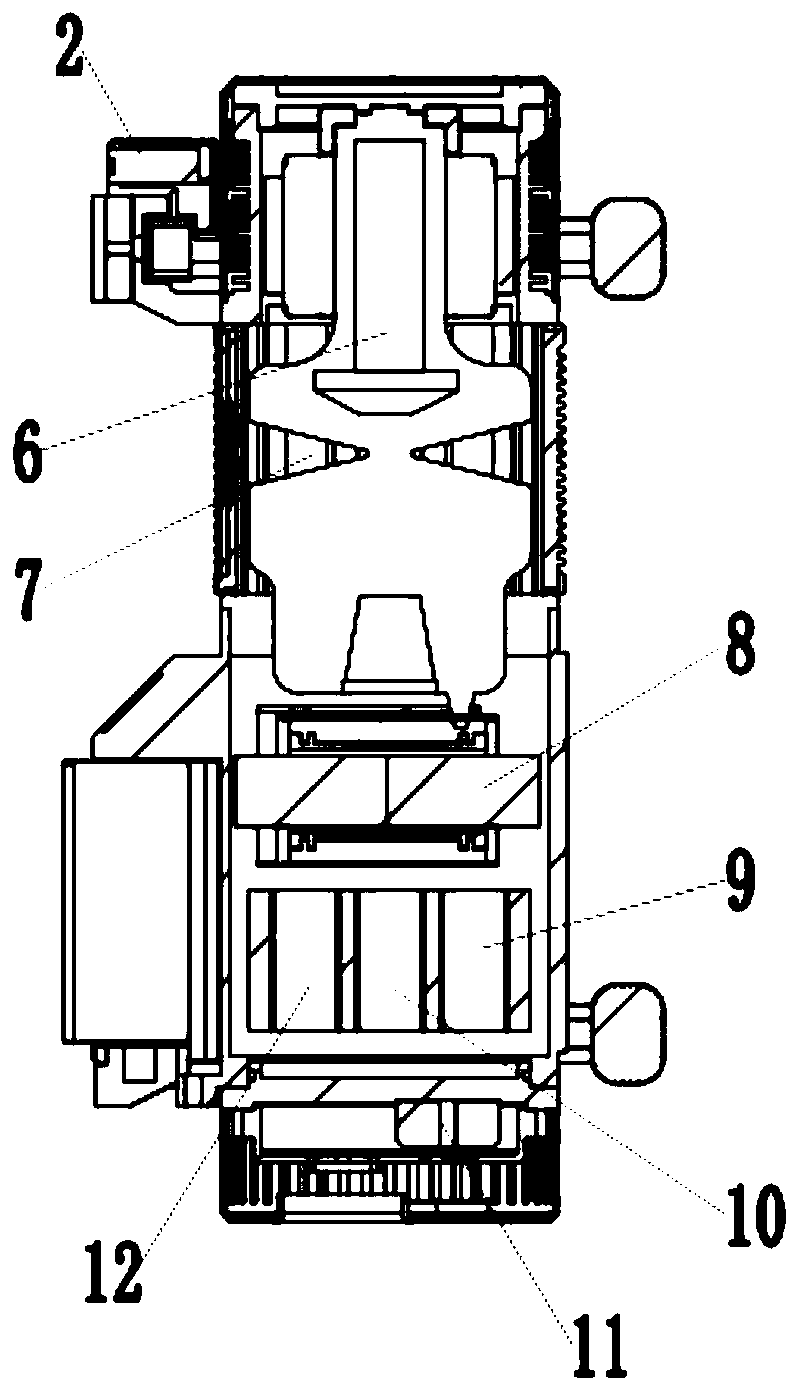
[0051] In order to further improve the working efficiency of the equipment, in this embodiment, the ray tube 6 adopts a rotating target ray tube. The rotating target ray tube is fixed and limited in the radial direction by the fixed sleeve, and positioning bolts are set on the casing 1 to limit the axial direction of the rotating target ray tube to ensure the reliability of use. The rotating target ray tube is driven by a rotating motor.
[0052] Compared with Embodiment 1, this embodiment uses a rotating target ray tube, which has a better cooling effect and better work efficiency than a fixed target ray tube, and avoids the fixed working point of the fixed target ray tube, which may be caused by excessive temperature after long-term irradiation. The breakdown problem increases the reliability of equipment use.
[0053] Additionally, if Image 6 As shown, the control system of UHF X-ray flaw detector includes J1900 embedded logic board, 2.4G wireless operation data transmiss...
PUM
 Abstract
Description
Claims
Application Information