Pull-out type glass kiln flue gas dust removal device and application

A glass kiln and dust removal device technology, which is applied in gas treatment, transportation and packaging, and dispersed particle filtration, etc. It can solve the problems of large solid particles sticking to the chimney and achieve the effects of simple structure, enhanced purification effect, and reduced solid particles.

Inactive Publication Date: 2020-06-26
QILU UNIV OF TECH
View PDF9 Cites 1 Cited by
  • Summary
  • Abstract
  • Description
  • Claims
  • Application Information

AI Technical Summary

Problems solved by technology

The equipment fails to clean the flue gas before it enters the chimney, which may easily cause large solid particles to stick and block the chimney

Method used


Image

  • Pull-out type glass kiln flue gas dust removal device and application
  • Pull-out type glass kiln flue gas dust removal device and application

Examples


Embodiment 1

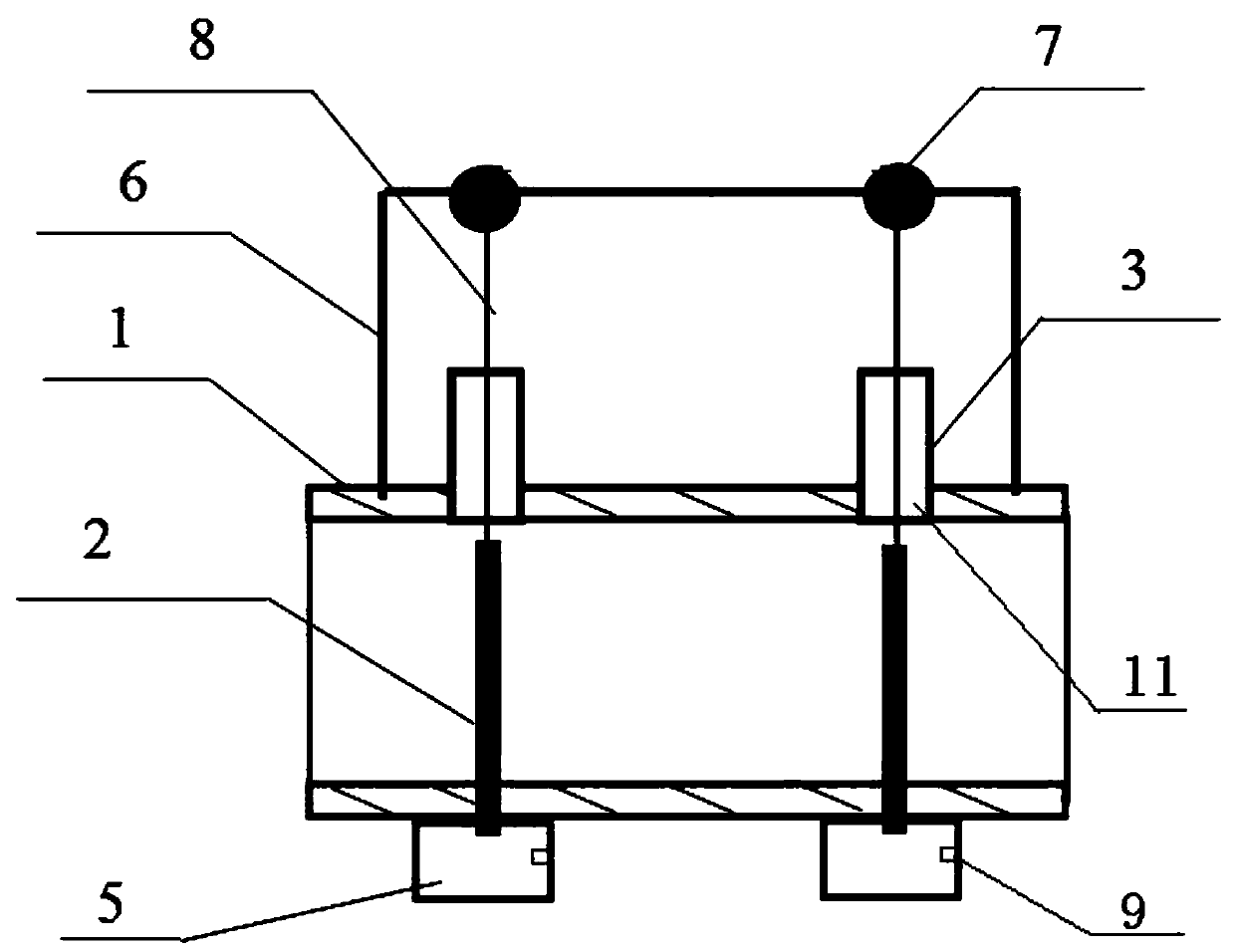
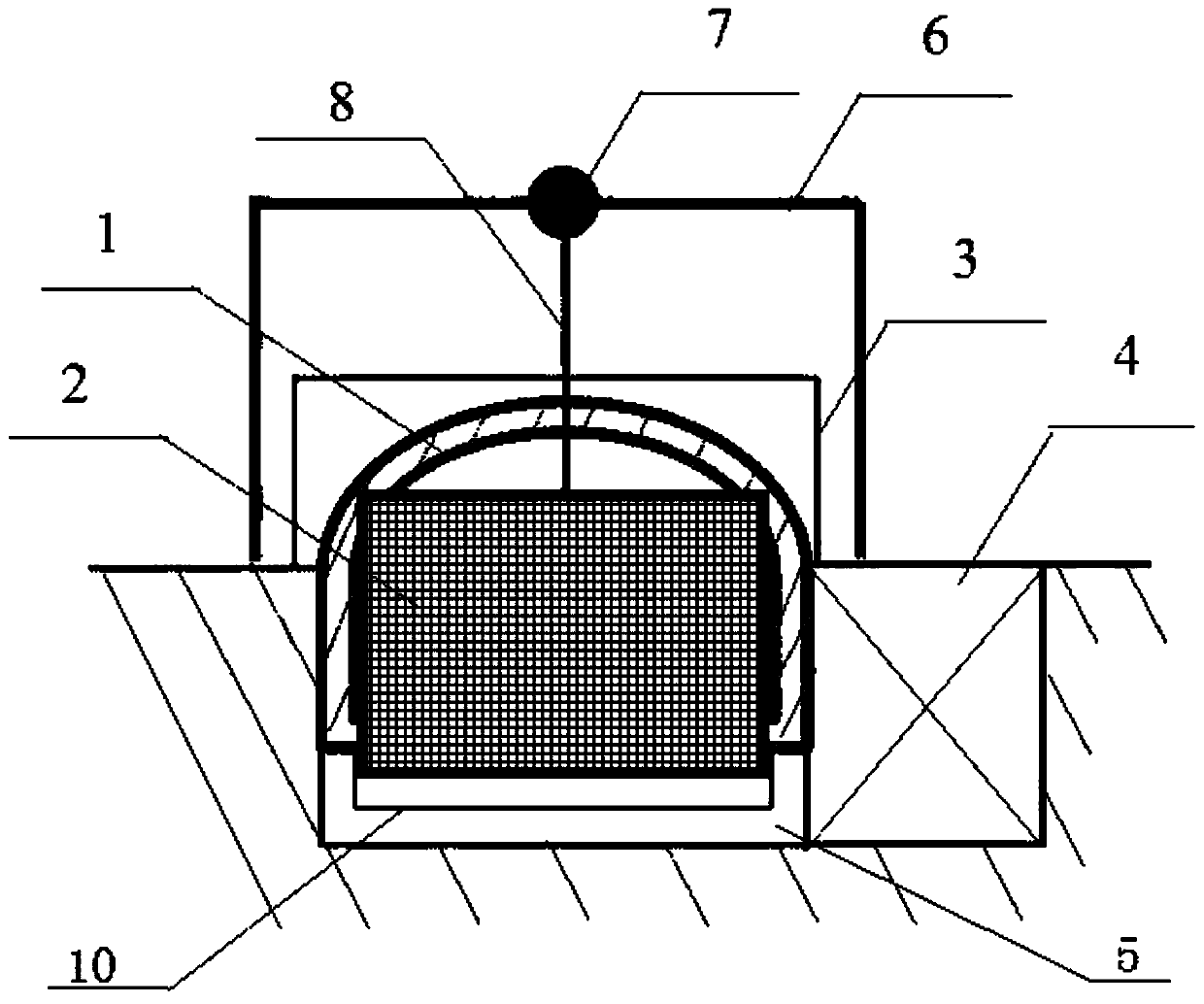
[0036] Such as Figure 1-2 As shown, the present embodiment provides a pull-type glass kiln flue gas dust removal device, including a flue 1, a grid 2, a transmission frame 6, a transmission wheel 7, a transmission chain 8 and a motor, and the flue 1 is Set the commutator and the general gate, between the commutator and the general gate, set the opening 11 above the flue 1 at a distance of 0.5m from the commutator, set slots on both sides of the flue opening 11, and grid 2 Insert the flue through the opening 11 and the slot, dig a corresponding rectangular ash collection pit 5 in the bottom of the flue 1 on the lower side of the grid 2, and set the ash pit 4 on one side of the flue 1, and the ash pit 4 is connected with the ash collection. The pit 5 is connected, and the transmission frame 6 is installed above the flue 1. The transmission frame 6 is a rectangular parallelepiped frame. A plurality of beams are arranged on the upper side of the transmission frame 6. A motor is i...

Embodiment 2

[0038] A pull-out glass kiln flue gas dust removal device, the structure is as described in Example 1, the difference is that between the commutator and the main gate, above the flue 1 at a distance of 1m from the commutator The opening 11 is set, and the sealing cover 3 is set on the upper side of the opening 11 of the flue 1. The sealing cover 3 is a cuboid as a whole, and the lower side of the sealing cover 3 fits the flue. The split-type airtight door is opened to both sides during the grille, and closed after the replacement is completed, and the airtight cover acts as a seal.

Embodiment 3

[0040] A pull-type glass kiln flue gas dust removal device, the structure is as described in Embodiment 1, the difference is that the grid hole diameter of the grid 2 is 10mm, and the grid 2 is made of alumina ceramic material. The double-layer structure strengthens the purification effect of flue gas, and alumina ceramics can withstand the high temperature of 600°C, ensuring that the grid will not be affected by the high temperature of flue gas.


PUM


Abstract

The invention relates to a pull-out type glass kiln flue gas dust removal device and application. The invention belongs to the technical field of glass production. The device comprises a flue, a grid,a transmission frame, transmission wheels, a transmission chain and a motor, wherein a reverser and a main gate plate are arranged on the flue; between the reverser and the main gate plate, an opening is formed in the position, 0.5-1 m away from the reverser, of the upper portion of the flue; slots are formed in two sides of an opening of the flue; the grid is inserted into the flue through the opening; a corresponding rectangular ash collecting pit is dug in the bottom of the flue on the lower side of the grid; an ash digging pit is formed in one side of the flue and communicated with the ash collecting pit; the transmission frame is installed above the opening of the flue, the transmission frame is a cuboid frame, a plurality of cross beams are arranged on the upper side of the transmission frame, motors are installed on the cross beams, output shafts of the motors are connected to transmission wheels, and the transmission wheels are connected to the grid through transmission chains. According to the invention, the grid is arranged in the flue to perform pre-dedusting on the flue gas before the flue gas enters a desulfurization and denitrification device, so that the purpose ofreducing solid particles carried in the flue gas is achieved, the working efficiency of cloth bag dedusting, desulfurization, denitrification and other flue gas subsequent treatment devices is improved, and the service lifetime of the cloth bag dedusting, desulfurization, denitrification and other flue gas subsequent treatment devices is prolonged.

Description

technical field [0001] The invention relates to a pull-type glass kiln flue gas dust removal device and its application, belonging to the technical field of glass production. Background technique [0002] With the requirements of environmental protection and sustainable development, the standard requirements for flue gas emission in the production process of glass products are also getting higher and higher. Among the flue gas emitted by glass furnaces, the main pollutants that can pollute the environment are solid particles, SO 2 , NO x In order to make the flue gas meet the emission standards, the flue gas needs to be dedusted, desulfurized, and denitrified. Since the flue gas contains more dust and other large solid particles, the large solid particles will pollute the desulfurization and denitrification devices during the flue gas desulfurization and denitrification process, reducing the desulfurization and denitrification effects and increasing the cost. Therefore, in...

Claims


Application Information

Patent Timeline
Patent Type & Authority Applications(China)
IPC IPC(8): B01D46/10B01D46/00B01D46/46B01D46/48
CPCB01D46/10B01D46/46B01D46/48B01D2258/0283B01D46/90
Inventor 刘建安沈建兴刘树江
Owner QILU UNIV OF TECH
Why Eureka
Try Eureka