Variable-diameter spiral groove type full-automatic optical part cleaning and washing device
A technology for optical parts and cleaning devices, applied in chemical instruments and methods, cleaning methods and utensils, cleaning methods using liquids, etc., can solve problems such as unfavorable cleaning, achieve simple structure, low manufacturing and operating costs, and eliminate cleaning dead corners Effect
- Summary
- Abstract
- Description
- Claims
- Application Information
AI Technical Summary
Problems solved by technology
Method used
Image

Examples
Embodiment 1
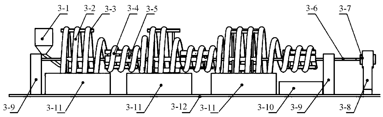
[0031] This embodiment provides an implementation manner of a transmission mechanism.
[0032] like image 3 , in actual operation, each component is placed on the workbench 3-12, and the transmission mechanism includes a cleaning screw support 3-3, a transmission screw support 3-5, a transmission shaft 3-6, two transmission shaft supports 3-9, a motor 3-7 and the motor support 3-8, the motor 3-7 is installed on the motor support 3-8, and the transmission shaft 3-6 is connected with the motor, and the two transmission shaft supports 3-9 are arranged on the The position where the variable-diameter spiral group is installed serves to support the transmission shaft 3-6 and the parts driven by the transmission shaft 3-6, and the position where the variable-diameter spiral group is installed is alternately provided with a cleaning screw support 3-3 and a transmission screw support 3- 5.
Embodiment 2
[0034] This embodiment provides an implementation manner of a variable-diameter spiral group on the basis of Embodiment 1.
[0035] In this embodiment, the variable-diameter spiral group includes a cleaning screw 3-2, a transmission screw 3-4, and a connecting screw. The cleaning screw 3-2 is installed on the cleaning screw support 3-3, and the transmission screw 3-4 is installed on the transmission screw. On the bracket 3-4, the cleaning screw 3-2 is connected by a connecting screw, and the cleaning tank station 3-11 is arranged below the cleaning screw 3-2.
[0036] Furthermore, in the actual process of cleaning optical parts, the cleaning time of optical parts in different washing solutions such as water washing, alkaline cleaning, and acid cleaning may be inconsistent. At this time, each spiral group can be formulated according to the cleaning time. The number of turns, the cleaning time to reach the target, the number of turns of the cleaning screw 3-2 in each variable-di...
Embodiment 3
[0040] In this embodiment, on the basis of Embodiment 2, the variable-diameter helical group is further limited.
[0041] The cross section of the cleaning spiral 3-2, the transmission spiral 3-4 and the connecting spiral of the variable diameter spiral group, such as Image 6 As shown, it is semicircular, U-shaped, rectangular and its width is slightly larger than the optical parts to be cleaned to ensure that the optical parts can roll freely in the tank; the material of the tank is made of acid and alkali resistant and organic solvent materials, such as polypropylene , metal plates with acid and alkali resistant protective coating, etc., dense small holes are opened on the tank body to discharge cleaning liquid.
PUM
 Abstract
Description
Claims
Application Information
 - R&D
- Intellectual Property
- Life Sciences
- Materials
- Tech Scout
- Unparalleled Data Quality
- Higher Quality Content
- 60% Fewer Hallucinations
Browse by: Latest US Patents, China's latest patents, Technical Efficacy Thesaurus, Application Domain, Technology Topic, Popular Technical Reports.
© 2025 PatSnap. All rights reserved.Legal|Privacy policy|Modern Slavery Act Transparency Statement|Sitemap|About US| Contact US: help@patsnap.com