Building viewing water curtain

A movie viewing and water curtain technology, which is applied to buildings, building components, building structures, etc., can solve the problems of power consumption of projection equipment and water pumps, increased power consumption, large power consumption and equipment consumption, and achieve faster water storage The effect of speed, reduction of power consumption, and stable water storage speed

Active Publication Date: 2020-06-26
王慧娟
View PDF6 Cites 0 Cited by
  • Summary
  • Abstract
  • Description
  • Claims
  • Application Information

AI Technical Summary

Problems solved by technology

[0004] The purpose of the present invention is to solve the disadvantages in the prior art that existing water curtain buildings require water pumps to work at full load for a long time, consume a

Method used


Image

  • Building viewing water curtain
  • Building viewing water curtain
  • Building viewing water curtain

Examples


Embodiment 1

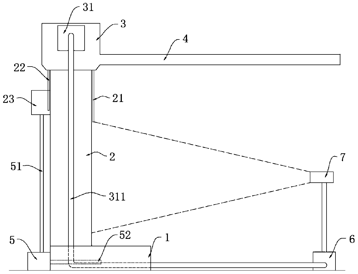
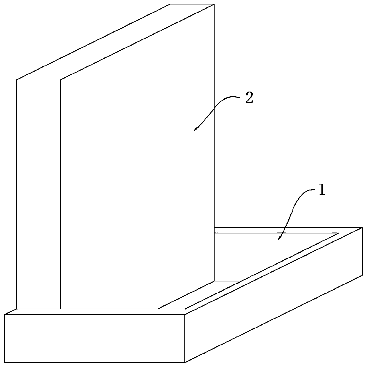
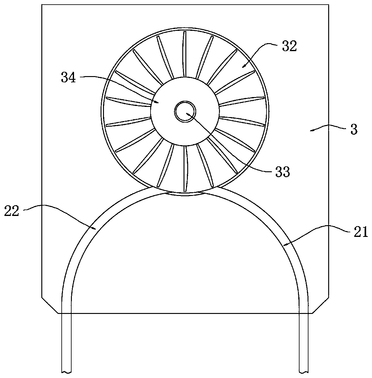
[0029] refer to Figure 1-4 , a water curtain for building viewing, including a water storage tank 1 and a power control box 6 installed on the ground, a curtain wall 2 is vertically installed in the water storage tank 1, a wall eaves 3 are installed on the upper end of the curtain wall 2, and the side walls of the wall eaves 3 A rain shelter 4 is installed on the top, a water storage tank 23 is installed on the upper left side of the curtain wall 2, a water pump 5 is installed on the left side of the curtain wall 2, and a water delivery pipe 51 is installed between the water pump 5 and the water storage tank 23. There is a water suction pipe 52, and the water suction pipe 52 extends into the water storage tank 1, a plurality of short pipes 22 and a plurality of long pipes 21 are installed on the left and right upper ends of the curtain wall 2 respectively, and there are equidistant pipes in the eaves 3. A plurality of circular grooves 32, a plurality of circular grooves 32 ar...

Embodiment 2

[0035] refer to Figure 5 , a building viewing water curtain, which is basically consistent with Embodiment 1, the difference is that:

[0036] The curtain wall 2 is fixedly installed with a porous support frame 11 on the side wall of the water storage tank 1, and the upper end of the porous support frame 11 is equipped with a water-absorbing sponge 12, and a water level sensor 13 is installed on the inner wall of the water storage tank 1, and the height of the water level sensor 13 is low. On the upper surface of the water-absorbing sponge 12, a drain pipe 14 is inserted on the side wall of the water storage tank 1, and a solenoid valve 15 is installed on the drain pipe 14;

[0037] The water flowing from the lower end of the long tube 21 falls freely onto the water-absorbing sponge 12, which can reduce the generation of water splashes and reduce the impact of water splashes on the water screen viewing, and the water falling on the water-absorbing sponge 12 can reduce the sou...


PUM


Abstract

The invention discloses a building viewing water curtain. The building viewing water curtain comprises a water storage tank and an electric control box, wherein the water storage tank and the electriccontrol box are mounted on the ground. A curtain wall is vertically mounted in the water storage tank, a wall eave is mounted at the upper end of the curtain wall, a water storage box is mounted at the upper end of the left side of the curtain wall, a water pump is mounted on the ground on the left side of the curtain wall, a water conveying pipe is mounted between the water pump and the water storage box, a water pumping pipe is mounted on the water pump, the water pumping pipe stretches into the water storage tank, and multiple short pipes and multiple long pipes are mounted at the upper ends of the left side and the right side of the curtain wall in an attached manner correspondingly. Siphoning is formed in the water storage box through the long pipes, the short pipes and round grooves, siphoning water currents drive impellers and rotary shafts to rotate for power generation, siphoning power generation is used for projection equipment, an electromagnetic valve and a water level sensor, the power consumption of water curtain viewing is reduced, due to the siphoning phenomenon, the water pump only needs to pump the water currents into the water storage box, the power consumptionof the water pump is reduced, and the power consumption of water curtain viewing is further reduced.

Description

technical field [0001] The invention relates to the field of movie viewing water curtains, in particular to an architectural movie viewing water curtain. Background technique [0002] With the growth of the economy, people pay more and more attention to leisure life, and often go to amusement parks, cultural tourism parks and other scenic spots. Modern large-scale scenic spots usually set up large screens for tourists to watch and understand related themes. Among them, the water screen The viewing effect is the most shocking. [0003] Existing water curtain buildings usually use water pumps and other equipment to pump the water flow above the building, and then the water flow falls to form a water curtain. The projection equipment projects the image data on the water curtain for playback, but this method requires the water pump to continue to work at full capacity. Power consumption and equipment consumption are large, and both water pumps and projection equipment need to c...

Claims


Application Information

Patent Timeline
IPC IPC(8): E04B2/88E03B1/00E03B3/02E04F10/00G03B21/608F03B13/06
CPCE03B1/00E03B3/02E04B2/88E04F10/00F03B13/06G03B21/608Y02E10/20Y02E60/16Y02A20/108
Inventor 王慧娟
Owner 王慧娟
Why Eureka
Try Eureka