
Automatic catwalk and method

A catwalk and sliding connection technology, which is applied in the direction of earthwork drilling, drilling equipment, instruments, etc., can solve the problems of low work efficiency, error-prone, time-consuming and labor-intensive, etc., to improve accuracy, improve safety, and ensure accuracy Effect

Active Publication Date: 2020-06-26
山东诚纳石油机械有限公司
View PDF6 Cites 2 Cited by
  • Summary
  • Abstract
  • Description
  • Claims
  • Application Information

AI Technical Summary

Problems solved by technology

[0002] During workover operations, the length of the tubing needs to be manually measured on site (the distance from the outside of the coupling to the threaded thread). There are a large number of tubing on site (hundreds of pieces), and two people are required to stand at both ends of the tubing and pull a tape to measure and record. Time-consuming, labor-intensive, low-efficiency, and error-prone

Method used


Image

  • Automatic catwalk and method
  • Automatic catwalk and method
  • Automatic catwalk and method

Examples


no. 1 approach

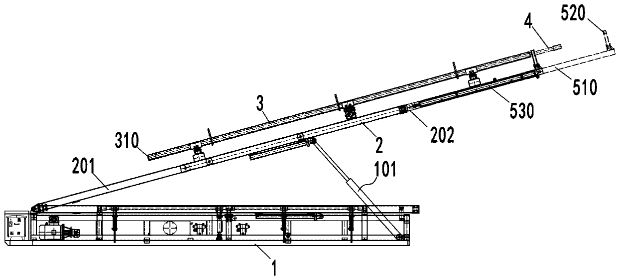
[0054] figure 1 It is a structural schematic diagram of an automated catwalk in an embodiment of the present invention, wherein the automated catwalk is in a falling state. figure 2 It is a structural schematic diagram of an automated catwalk in an embodiment of the present invention, wherein the automated catwalk is in a lifting state.

[0055] Such as figure 1 and figure 2 As shown, an automated catwalk includes: a frame 1, a lifting bracket 2, an accommodating slot 3 and a length measuring mechanism 5.

[0056]Wherein, the lifting bracket 2 is connected with the frame 1; the receiving slot 3 is slidably connected with the lifting bracket 2. Specifically, the lifting support 2 includes a first frame body 201, a second frame body 202 and a telescopic hydraulic cylinder 14, the first frame body 201 is pivotally connected with the frame 1, and the second frame body 202 and the first frame body 201 are slidable connected, and the extension direction of the second frame bod...

no. 2 approach

[0087] During the implementation of the technical solution of the present invention, the inventor found that when the first baffle 310 and the second baffle 520 clamp the pipe 4, the middle part of the pipe 4 will bend, which will affect the accuracy of the measurement, and may even It will cause a safety accident.

[0088] In order to solve the above technical problems, the technical solution of the present invention further includes a safety righting mechanism 6 . Figure 6 It is a schematic structural diagram of the safety righting mechanism 6 in an automated catwalk according to an embodiment of the present invention, wherein the safety righting mechanism 6 is in an open state. Figure 7 The safety righting mechanism 6 in the closed state.

[0089] Such as Figure 6 and Figure 7 As shown, the safety righting mechanism 6 includes a righting arm 601 and a righting hydraulic cylinder 603 . One end of the righting liquid cylinder 603 is pivotally connected to the first en...

no. 3 approach

[0091] Such as Figure 9 As shown, a method for measuring the length of a pipe using an automated catwalk mainly includes the following steps:

[0092]S200, clamping the pipe 4 in the length direction of the pipe 4;

[0093] S400, acquiring displacement information of the piston rod of the length measuring cylinder 530;

[0094] S600. Calculate the length of the pipe 4 according to the displacement information.

[0095] Further, as Figure 10 As shown, before the step S200 of clamping the pipe in the length direction of the pipe 4, it also includes:

[0096] S100 , make the second baffle 520 face the first baffle 310 .

[0097] Specifically, the first baffle 310 is fixed at one end of the receiving slot 3 , and the second baffle 520 can rotate or move to a position opposite to the first baffle 310 , so as to clamp the pipe 4 .

[0098] Further, before the step of clamping the pipe 4 in the length direction of the pipe 4 includes:

[0099] Righting the pipe so that the pi...


PUM


Abstract

The invention discloses an automatic catwalk and a method, and relates to the technical field of oilfield equipment. The automatic catwalk comprises a machine frame, a lifting support, a containing groove, a length measuring mechanism and a control unit. The lifting support is connected with the machine frame, the containing groove is in sliding connection with the lifting support, the containinggroove comprises a first end part and a second end part which are arranged oppositely, the first end part is provided with a first baffle, the length measuring mechanism is connected with the liftingsupport, and located on the second end part side of the containing groove, the length measuring mechanism comprises a telescopic part, a second baffle and a length measuring hydraulic cylinder, the telescopic part is in sliding connection with the lifting support, one end of the length measuring hydraulic cylinder is connected with the lifting support, the other end of the length measuring hydraulic cylinder is connected with the telescopic part, the second baffle is connected with the telescopic part, the length measuring hydraulic cylinder comprises a first displacement sensor, the first displacement sensor is used for measuring displacement information of a piston rod of the length measuring hydraulic cylinder, and the control unit is connected with the first displacement sensor and used for calculating the length of a pipe according to the displacement information detected by the first displacement sensor.

Description

technical field [0001] The invention relates to the technical field of petroleum equipment, in particular to an automatic catwalk and a method for measuring the length of a pipe. Background technique [0002] During workover operations, the length of the tubing needs to be manually measured on site (the distance from the outside of the coupling to the threaded thread). There are a large number of tubing on site (hundreds of pieces), and two people are required to stand at both ends of the tubing and pull a tape to measure and record. Time-consuming, labor-intensive, low-efficiency, and error-prone. Contents of the invention [0003] The invention aims at the deficiencies of the prior art, and provides an automatic catwalk, which improves the working efficiency and the accuracy of measurement. [0004] A kind of automatic catwalk provided by the present invention comprises frame and lifting support, and described lifting support is connected with described frame; Described...

Claims


Application Information

Patent Timeline
IPC IPC(8): E21B19/14G01B21/02
CPCE21B19/14G01B21/02
Inventor 田冠军范新冉潘龙飞曹文瀚马聪田艳君胡军芳李龙叶嘉明赵广平刘冠辰刘东利姜文灏李晓冉曹晓林姚卫岩崔振裕冯庆涛
Owner 山东诚纳石油机械有限公司
Learn More