Mixed vibration control device and method based on negative stiffness and variable damping and application

A negative stiffness and variable technology, applied in the direction of vibration suppression adjustment, non-rotational vibration suppression, shock absorbers, etc., can solve the problems of unavailable, high reliability, low cost, etc., and achieve high reliability without affecting stability , low cost effect

Active Publication Date: 2020-06-26
CHINA UNIV OF PETROLEUM (EAST CHINA)
View PDF8 Cites 10 Cited by
  • Summary
  • Abstract
  • Description
  • Claims
  • Application Information

AI Technical Summary

Problems solved by technology

Inspired by this conclusion, the present invention is based on a hybrid vibration control device with negative stiffness and variable damping, combining negative stiffness with semi-active control, and using negative stiffness to solve the problem that semi-active control cannot provide a damping force in the same direction as the vibration v

Method used


Image

  • Mixed vibration control device and method based on negative stiffness and variable damping and application
  • Mixed vibration control device and method based on negative stiffness and variable damping and application
  • Mixed vibration control device and method based on negative stiffness and variable damping and application

Examples


Embodiment 1

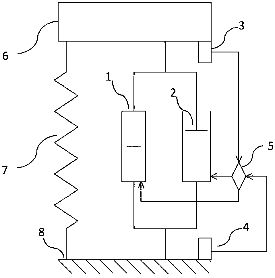
[0090] Taking the vibration isolation table as an example, the vibration isolation table is simulated as a single-degree-of-freedom system, and the present invention is installed in the vibration isolation table, arranged in parallel with the support spring 7 of the vibration isolation table, one end is connected to the sprung element 6, and the other end is connected to the base 8 .

[0091] The relevant parameters are: the sprung element 6 is 1 kg, the stiffness of the supporting spring 7 is 3000N / m, the stiffness coefficient of the negative stiffness element 1 is -2400N / m, the minimum damping coefficient that the variable damping element 2 can provide is 2Ns / m, the maximum The damping coefficient is 50Ns / m, the control algorithm is a linear quadratic regulator (LQR), and the base input excitation is velocity white noise.

[0092] Figure 12 It is the absolute vibration velocity time course diagram of the sprung element 6 of the vibration isolation table, comparing the vibr...

Embodiment 2

[0096] The invention can also be applied to vehicle suspensions. refer to Figure 19 , the vehicle is simulated as a commonly used 1 / 4 vehicle dual-degree-of-freedom system, the hybrid vibration control device of the present invention is installed in the vehicle suspension, so that it is arranged in parallel with the suspension system of the vehicle, the vehicle body 9, the vehicle chassis 10. The vehicle tires 11 are installed under the vehicle chassis 10, and the support spring 7 for reducing the vibration effect and the hybrid vibration control device of the present invention are installed between the vehicle chassis 10 and the vehicle body 9.

[0097] The relevant parameters are: the mass of the vehicle body 9 is 504.5kg, the mass of the vehicle chassis 10 is 62kg, the stiffness of the suspension support spring 7 is 13.1kN / m, the stiffness coefficient between the vehicle chassis 13 and the ground is 252kN / m, and the input excitation is velocity white noise. The control a...


PUM

PropertyMeasurementUnit
Stiffnessaaaaaaaaaa
Stiffness coefficientaaaaaaaaaa
Stiffnessaaaaaaaaaa

Abstract

The invention provides a mixed vibration control device and method based on negative stiffness and variable damping and application. The device comprises a negative stiffness component and a variabledamping component connected in parallel between a component on a reed and a component under the reed, a sensor I for measuring vibration of the component on the reed and transferring vibration information, a sensor II for measuring vibration of the component under the reed or a substrate and transferring vibration information, and a controller. The controller receives the vibration information ofthe sensors I and II and adjusts the stiffness coefficient of the negative stiffness component and the damping coefficient of the variable damping component according to attribute parameters of a structure and a control algorithm. The mixed vibration control device solves the problem that semi-active control cannot provide a control force, the direction of which is as same as a vibrating speed direction, so as to execute the control algorithm to obtain the optimum theoretical control force integrally, thereby obtaining a vibration control effect as same as that of active control.

Description

technical field [0001] The invention relates to the field of vibration control, in particular to a hybrid vibration control device, method and application based on negative stiffness and variable damping. Background technique [0002] Dynamic loads can cause many hazards, ranging from reduced vehicle comfort to structural damage and collapse caused by earthquakes. In order to protect the main structure and reduce the vibration caused by dynamic loads, various vibration control technologies have emerged as the times require. Vibration control technology can be roughly divided into three modes: passive, semi-active and active. [0003] Passive control does not require sensors and power sources, but its control force is only determined by the response of the structure itself, and the kinetic energy of the structure is dissipated through the damping force. Common passive control devices include viscous dampers, friction dampers, eddy current dampers, tuned mass dampers, etc. ...

Claims


Application Information

Patent Timeline
IPC IPC(8): F16F15/02F16F15/027F16F15/04
CPCF16F15/002F16F15/022F16F15/027F16F2230/0005F16F2230/08F16F2230/18F16F2222/04F16F2222/12F16F2224/043F16F2224/045F16F2228/063
Inventor 石翔
Owner CHINA UNIV OF PETROLEUM (EAST CHINA)
Why Eureka
Try Eureka