Energy recovery gas-liquid two-phase circulating cooling system

An energy recovery and cooling system technology, applied in the field of high temperature component cooling, can solve the problems of low heat resource recovery and utilization efficiency, complex structure of water cooling system, limited heat capacity, etc. Inflow smooth effect

Pending Publication Date: 2020-06-26
JIANGSU UNIV +1
View PDF8 Cites 3 Cited by
  • Summary
  • Abstract
  • Description
  • Claims
  • Application Information

AI Technical Summary

Problems solved by technology

Traditional air cooling technology, due to the low density of the cooling gas, the density is usually 1-2kg / m at normal temperature and pressure 3 , the specific heat is about 1kJ / kg, so its heat capacity is limited, the heat conduction efficiency is extremely poor, and the fan will generate noise during operation
The same volume of water and cooling gas absorb the same amount of heat, and the cooling gas temperature rises about 4,000 times that of water. However, in many cases, the cooling area cannot be in direct contact with water. It is difficult to operate water cooling through cooling pipes, and the structure of the water cooling system is relatively Complicated and inefficient in recycling heat resources

Method used


Image

  • Energy recovery gas-liquid two-phase circulating cooling system
  • Energy recovery gas-liquid two-phase circulating cooling system
  • Energy recovery gas-liquid two-phase circulating cooling system

Examples


Embodiment Construction

[0023] The technical solution of the present invention will be described in further detail below in conjunction with the accompanying drawings.

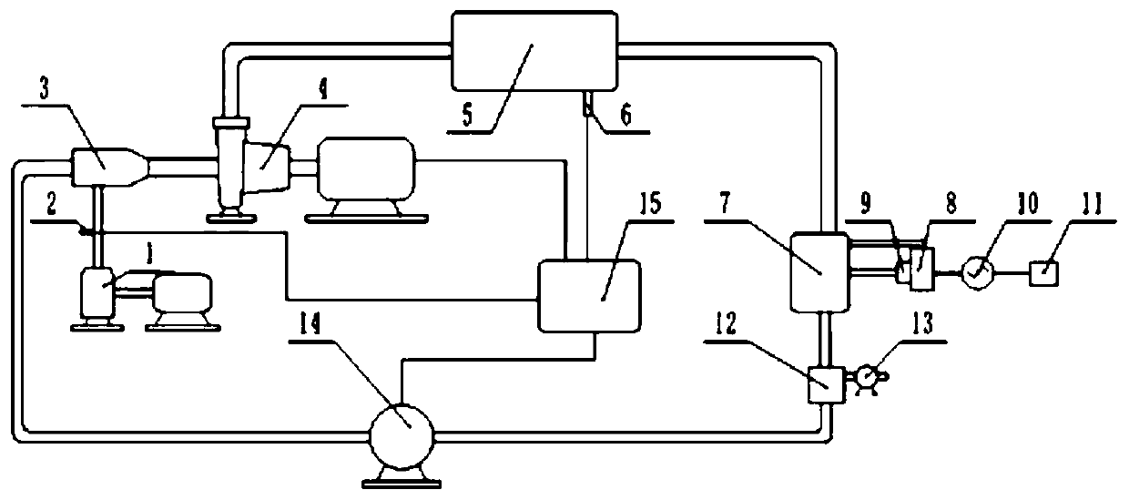
[0024] combine figure 1 , an energy recovery gas-liquid two-phase circulating cooling system provided in this embodiment includes: a first compressor 1, a gas flow controller 2, a gas-liquid mixer 3, an atomizing pump 4, a cooling zone 5, and a temperature sensor 6 , tube-fin heat exchanger 7, expander 8, compressor 9, generator 10, battery 11, gas-liquid separator 12, air pump 13, liquid delivery pump 14, controller 15. The outlet of the first compressor 1 is connected to the gas flow controller 2 and the inlet pipe of the gas-liquid mixer 3 through the gas pipeline, the gas-liquid mixer 3 is connected to the inlet of the atomizing pump 4 through the gas-liquid mixing pipeline, and the outlet of the atomizing pump 4 passes through The gas-liquid mixing pipeline is connected to the inlet of the cooling zone 5, the cooling zone 5 is ...


PUM


Abstract

The invention discloses an energy recovery gas-liquid two-phase circulating cooling system which comprises a first compressor, a gas flow controller, an atomizing pump, a cooling area, a temperature sensor, a fin tube heat exchanger, a second expansion machine, an electric generator, a storage battery, a gas-liquid separator, an air pump, a liquid delivery pump and a controller. A micropore in thesurface of the impeller outlet of the atomizing pump atomizes low temperature gas-liquid two-phase flow into a low temperature high-pressure gas-liquid mixture, and the low temperature high-pressuregas-liquid mixture can be in direct contact with the cooling area for heat dissipation; the fin tube heat exchanger absorbs the heat of high-temperature high-pressure gas-steam mixture for power generation, and the generated electric energy is stored in storage battery to be used by power generation equipment in the cooling system; after heat dissipation and pressure drop of the high-temperature high-pressure gas-steam mixture in the fin tube heat exchanger, the high-temperature high-pressure gas-steam mixture enters the gas-liquid separator; after gas-liquid separation, deionized water entersthe liquid delivery pump, the air flows into the external environment, and the operation condition of the entire system is adjusted by the controller.

Description

technical field [0001] The invention relates to an energy recovery gas-liquid two-phase circulation cooling system, which is suitable for cooling high-temperature components such as aerospace equipment, large-scale electronic equipment, and electric furnace lining. Background technique [0002] Cooling and temperature control systems for aerospace equipment, large electronic equipment and electric furnace linings face technical requirements in terms of high heat dissipation efficiency, precise temperature control, energy saving, compact structure, and low noise. Traditional air cooling technology, due to the low density of the cooling gas, the density is usually 1-2kg / m at normal temperature and pressure 3 , the specific heat is about 1kJ / kg, so its heat capacity is limited, the heat conduction efficiency is extremely poor, and the fan will generate noise during operation. The same volume of water and cooling gas absorb the same amount of heat, and the cooling gas temperatu...

Claims


Application Information

Patent Timeline
IPC IPC(8): F25B25/00F25B49/02F01K27/00F01K25/10F01D15/10F01D15/08
CPCF01D15/08F01D15/10F01K25/10F01K27/00F25B25/00F25B49/02
Inventor 司乔瑞廖敏泉王彪彪袁建平袁寿其
Owner JIANGSU UNIV
Why Eureka
Try Eureka