Y waveguide parameter measuring instrument, Y waveguide parameter measuring system and Y waveguide parameter measuring method

A parameter measurement and waveguide technology, applied in the field of measurement, can solve the problems of high price, accuracy of measurement results, low stability and reliability, single measurement parameter, etc., achieve low cost, realize multi-parameter measurement, and simple measurement steps Effect

Pending Publication Date: 2020-06-26
北京世维通光智能科技有限公司
View PDF0 Cites 2 Cited by
  • Summary
  • Abstract
  • Description
  • Claims
  • Application Information

AI Technical Summary

Problems solved by technology

Due to the imperfect and immature equipment functions, the measurement efficiency is low, and the error caused by human factors cannot be ignored, resulting in a large difference between the actual measured value and the real value, and the accuracy, stability and reliability of the measurement results are generally low. At the same time, the existing waveguide tester has complex testing process, single measurement parameter and high price

Method used


Image

  • Y waveguide parameter measuring instrument, Y waveguide parameter measuring system and Y waveguide parameter measuring method
  • Y waveguide parameter measuring instrument, Y waveguide parameter measuring system and Y waveguide parameter measuring method
  • Y waveguide parameter measuring instrument, Y waveguide parameter measuring system and Y waveguide parameter measuring method

Examples


Embodiment 1

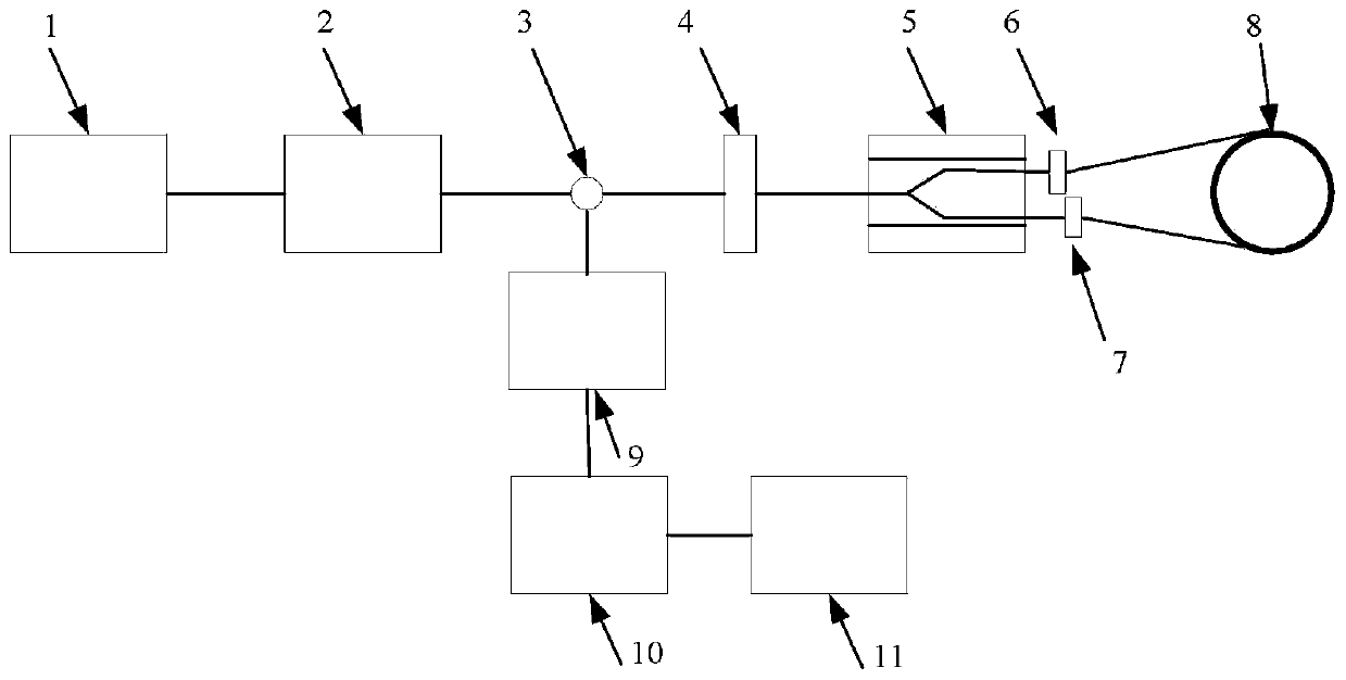
[0049] Such as figure 1 As shown, the Y waveguide parameter measuring instrument of this embodiment includes: a light source 1 , an adjustable optical attenuator 2 , a circulator 3 , an optical detector 9 , an optical path conversion device and a host computer 11 .

[0050] The output end of the light source 1 is connected to the input end of the adjustable optical attenuator 2, and the output end of the adjustable optical attenuator 2 is connected to the first port of the circulator 3; the second port of the circulator 3 The port is connected to one end of the trunk of the Y-waveguide 5 to be tested; the other end of the trunk is connected to an end of the first bifurcation of the Y-waveguide 5 to be tested and an end of the second bifurcation of the Y-waveguide 5 to be tested respectively The other end of the first bifurcation is connected to the first port of the optical path conversion device; the other end of the second bifurcation is connected to the second port of the o...

Embodiment 2

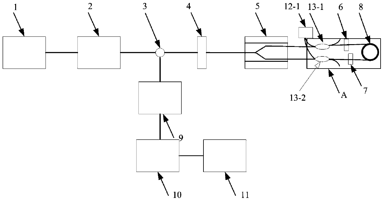
[0061] Such as figure 2 As shown, the difference between this embodiment and the above embodiments is that this embodiment also includes: a first dual-channel optical power meter 12-1, a first coupler 13-1 and a second coupler 13-2, the first The splitting ratio of the first coupler 13-1 is the same as that of the second coupler 13-2.

[0062] The other end of the first branch is connected to the first port of the first coupler 13-1, and the second port of the first coupler 13-1 is connected to the first port of the optical path conversion device; The third port of the first coupler 13-1 is connected to the first input end of the first dual-channel optical power meter 12-1; the other end of the second bifurcation is connected to the second coupler 13-2 The first port, the second port of the second coupler 13-2 is connected to the second port of the optical path conversion device; the third port of the second coupler 13-2 is connected to the first dual-channel optical power ...

Embodiment 3

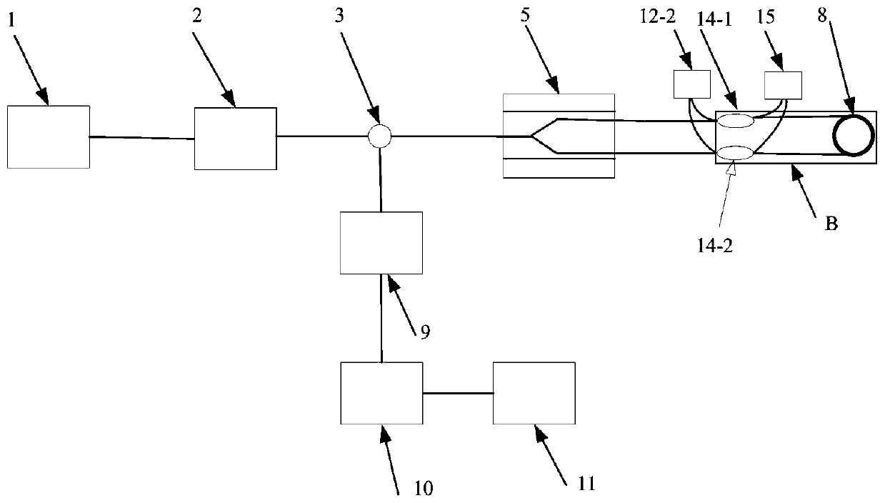
[0067] Such as image 3 As shown, the difference between this embodiment and the above embodiments is that this embodiment also includes: a first polarizing beam splitter 14-1, a second polarizing beam splitter 14-2, a second dual-channel optical power meter 12-2 And a dual-channel extinction ratio measuring instrument 15.

[0068] The first port of the first polarization beam splitter 14-1 is connected to the other end of the first branch, and the second port of the first polarization beam splitter 14-1 is connected to the first end of the optical path conversion device. port, the third port of the first polarization beam splitter 14-1 is connected to the first input end of the second dual-channel optical power meter 12-2, and the fourth port of the first polarization beam splitter 14-1 The port is connected to the first input end of the dual-channel extinction ratio measuring instrument 15; the first port of the second polarization beam splitter 14-2 is connected to the oth...


PUM


Abstract

The invention relates to a Y waveguide parameter measuring instrument, a Y waveguide parameter measuring system and a Y waveguide parameter measuring method. The Y waveguide parameter measuring instrument comprises a light source, a variable optical attenuator, a circulator, an optical detector, an optical path conversion device and an upper computer. The output end of the light source is connected with the input end of the variable optical attenuator, and the output end of the variable optical attenuator is connected with the first port of the circulator; a second port of the circulator is connected with one end of the trunk of the Y waveguide to be measured; the other end of the trunk is connected with one end of the first fork of the Y waveguide to be measured and one end of the secondfork of the Y waveguide to be measured; the other end of the first fork is connected with a first port of the light path conversion device; the other end of the second fork is connected with a secondport of the light path conversion device; a third port of the circulator is connected with the input end of the optical detector; the output end of the optical detector is connected with the upper computer. According to the invention, multi-parameter measurement is realized based on a measurement method of a traditional Sagnac interferometer, the measurement steps are simple, the cost is greatly reduced, and one-key full-automatic measurement is realized.

Description

technical field [0001] The invention relates to the field of measurement, in particular to a Y waveguide parameter measuring instrument, a measuring system and a measuring method. Background technique [0002] Y-branch optical modulator, also known as Y-waveguide phase modulator, or Y-waveguide for short, is a special modulation device for fiber optic gyro, and has a wide range of applications in the fields of fiber optic sensing and photoelectric signal processing. The principle of the Y waveguide is that the applied voltage signal generates a modulation electric field through the electrodes on both sides of the Y waveguide, thereby changing the effective refractive index of the waveguide and realizing the phase modulation of the transmitted optical signal. The key parameters of the Y waveguide include half-wave voltage, waveform slope, splitting ratio, extinction ratio, insertion loss, etc. [0003] The half-wave voltage is the amount of change required to cause the bias ...

Claims


Application Information

Patent Timeline
Patent Type & Authority Applications(China)
IPC IPC(8): G01C25/00G01M11/02G02B6/26G02B6/27
CPCG01C25/005G01M11/02G02B6/266G02B6/2746G02B6/276G02B6/2773
Inventor 刘凡李建光刘东伟王强龙肖浩刘博阳雷军
Owner 北京世维通光智能科技有限公司
Why Eureka
Try Eureka