Optical fiber laser hydrophone

A fiber laser and hydrophone technology, which is applied in instruments, measuring devices, and measuring ultrasonic/sonic/infrasonic waves, etc., can solve the problems of fiber laser hydrophone sensitivity changes, pre-tightening force and tensile force decay, and packaging structure zero. There are many components, etc., to achieve the effect of simplifying the packaging structure and packaging process, improving precision and packaging consistency

Active Publication Date: 2020-06-26
QINGDAO NAT LAB FOR MARINE SCI & TECH DEV CENT
View PDF60 Cites 2 Cited by
  • Summary
  • Abstract
  • Description
  • Claims
  • Application Information

AI Technical Summary

Problems solved by technology

[0006] At present, the basic idea of ​​fiber laser hydrophone sensitization is to design and fix the structure of the "active" fiber grating, so that the "active" fiber grating will produce as much deformation as possible under the action of sound pressure, thereby producing a larger Wavelength drift is used to improve the sensitivity of fiber laser hydrophones. Therefore, fiber laser hydrophone probes usually use end-face stretching for sensitivity enhancement. However, the technical solution for end-face stretching for sensitivity enhancement usually requires bonding optical fibers between On the diaphragm at the end, to form an end-face tension-type sensitization structure, correspondingly, the pre-tightening force of the packaging structure and the tensile force of the packaging part are also guaranteed by the adhesive part of the diaphragm. The characteristics lead to the decline of pre-tightening force and tensile force, which in turn leads to changes in the sensitivity of fiber laser hydrophones. Moreover, there are many structural components in the package, which leads to complicated packaging process, including the process of using glue, resulting in poor process consistency.

Method used


Image

  • Optical fiber laser hydrophone
  • Optical fiber laser hydrophone
  • Optical fiber laser hydrophone

Examples


Embodiment Construction

[0038] Hereinafter, the present invention will be described in detail through exemplary embodiments. However, it should be understood that without further description, the elements, structures, and features in one embodiment can also be beneficially combined into other embodiments.

[0039] In the description of the present invention, it should be noted that the terms "inner", "outer", "upper", "lower", "front", "rear", "left", "right", etc. indicate the orientation or position The relationship is based on the positional relationship shown in the drawings, which is only for the convenience of describing the present invention and simplifying the description, rather than indicating or implying that the device or element referred to must have a specific orientation, be constructed and operated in a specific orientation, and therefore cannot be understood To limit the present invention. In addition, the terms "first", "second", and "third" are only used for descriptive purposes, and...


PUM


Abstract

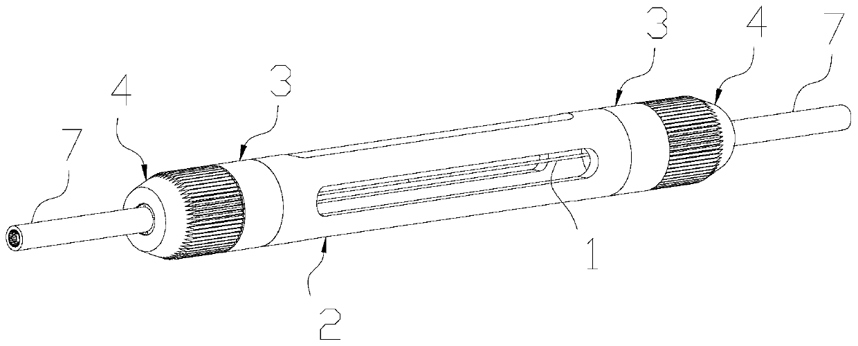
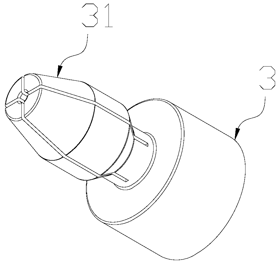
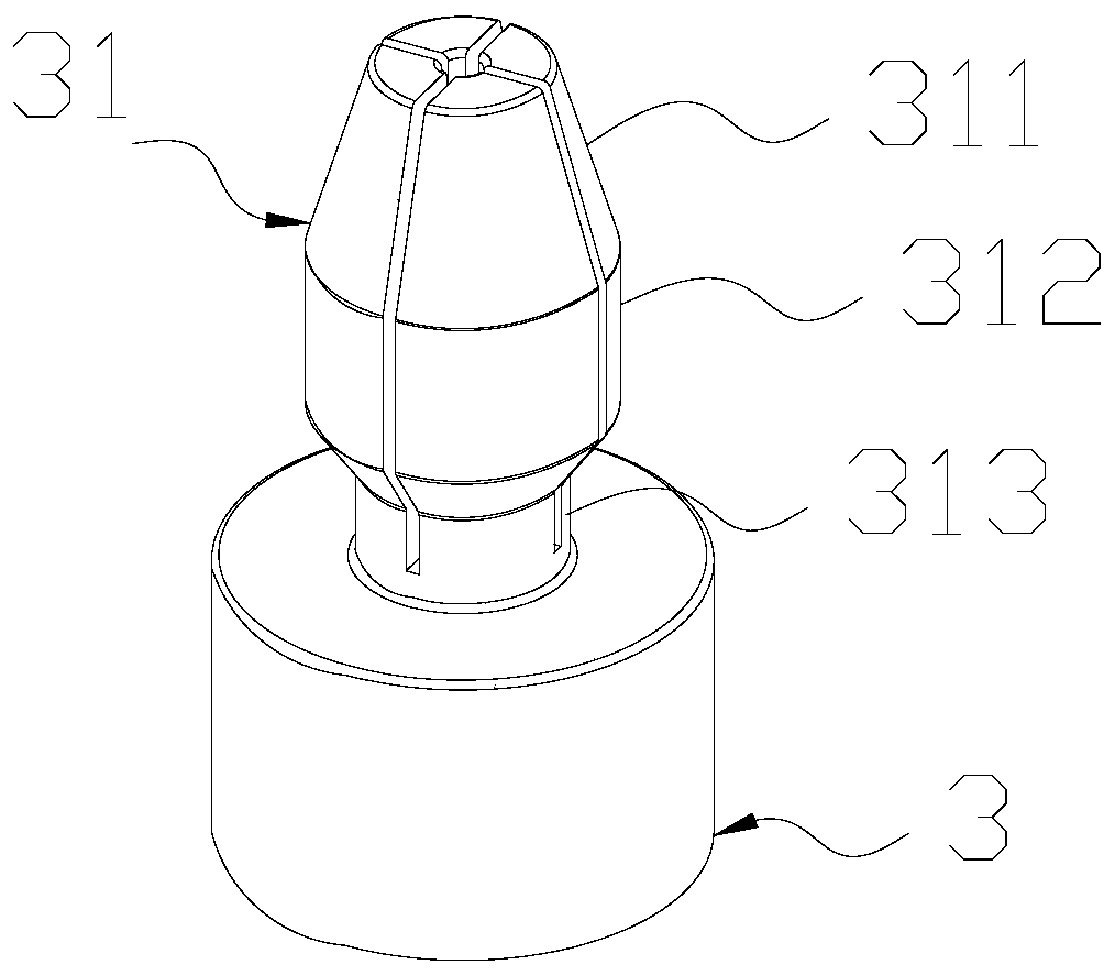
The invention provides an optical fiber laser hydrophone, which comprises an optical fiber provided with a phase shift fiber bragg grating, an acoustic transmission protective sleeve, locking ends, protection ends, and clamping jaws. The locking ends are connected to the two ends of the acoustic transmission protective sleeve, and at least two clamping jaws are arranged at the ends, away from theacoustic transmission protective sleeve, of the locking ends. The protection ends sleeve the locking ends; an optical fiber is arranged in the acoustic transmission protection sleeve in a communicating mode, the two ends of the optical fiber penetrate through the locking end and penetrate out of the protection end, and when the protection ends sleeve the locking ends , the clamping jaws are foldedto clamp the optical fiber. With the clamping jaws, when the protection ends sleeve the locking ends, the clamping jaws are folded to clamp the optical fiber; the pre-tightening force acting on the optical fiber can be kept for a long time; the sensitivity of the hydrophone is kept for a longer time, the pretightening force is kept in a mechanical clamping mode, the pretightening force is convenient and quantifiable to apply, glue is prevented from being used in the optical fiber fixing process, pretightening force keeping and environment protection are facilitated, the packaging structure and process are simplified, and the packaging efficiency and packaging quality are improved.

Description

Technical field [0001] The invention relates to the technical field of fiber laser hydrophones, in particular to a fiber laser hydrophone. Background technique [0002] Unmanned underwater vehicles (Unmanned underwater vehicles, referred to as: UUVs) are devices that are unmanned, remotely controlled or automatically controlled to navigate underwater. They mainly refer to those that replace divers or manned small submarines for deep-sea detection, life-saving, mine removal, etc. Intelligent system for dangerous underwater operations. [0003] In view of the cost advantage of UUV, it has become a development trend at home and abroad that UUV carries towed sonar for detection tasks. Towed linear array sonar is abbreviated as "towed array sonar". It is a sonar that arranges hydrophones in a linear array and is dragged by a towed cable behind the vehicle for underwater target detection. Its advantages are: large array size, The working frequency is low, which is conducive to line spe...

Claims


Application Information

Patent Timeline
Patent Type & Authority Applications(China)
IPC IPC(8): G01H9/00
CPCG01H9/004
Inventor 张海岩赵俊鹏赵晨郑百超张宇飞姚树智王颖
Owner QINGDAO NAT LAB FOR MARINE SCI & TECH DEV CENT
Why Eureka
Try Eureka