Light intensity detection circuit, light intensity detection method and device

A light intensity detection and circuit technology, which is applied in the direction of measuring devices, measuring circuits, photometry, etc., can solve the problems of sensitivity differences and poor uniformity of pixel units, and achieve the effect of eliminating sensitivity differences and improving uniformity

Active Publication Date: 2021-11-16
BOE TECH GRP CO LTD +1
View PDF5 Cites 0 Cited by
  • Summary
  • Abstract
  • Description
  • Claims
  • Application Information

AI Technical Summary

Problems solved by technology

[0004] However, since the amplification gain of each pixel unit is related to the threshold voltage of the amplifying transistor in each pixel unit, and the threshold voltage of each amplifying transistor is different due to the drift phenomenon, the sensitivity between different pixel units is different, that is, each pixel unit poor uniformity

Method used


Image

  • Light intensity detection circuit, light intensity detection method and device
  • Light intensity detection circuit, light intensity detection method and device
  • Light intensity detection circuit, light intensity detection method and device

Examples


no. 1 example

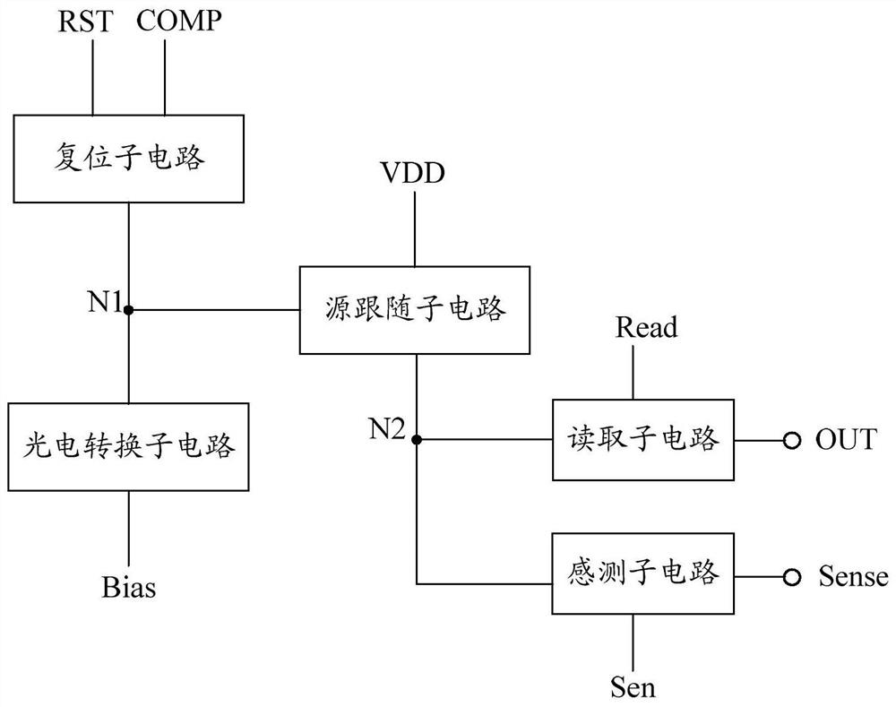
[0049] figure 1 It is a schematic structural diagram of the light intensity detection circuit of the first embodiment of the present application. like figure 1 As shown, the light intensity detection circuit of this embodiment includes: a photoelectric conversion sub-circuit, a source-following sub-circuit, a reset sub-circuit, a reading sub-circuit and a sensing sub-circuit.

[0050] Specifically, the photoelectric conversion sub-circuits are respectively connected to the bias voltage terminal Bias and the first node N1, and are used to generate corresponding electrical signals according to the incident light signal, and output them to the first node N1; the source follower sub-circuits are respectively connected to the first node N1 , the first voltage terminal VDD is connected to the second node N2, and is used to generate a corresponding voltage signal or current signal according to the electrical signal of the first node N1 and output it to the second node N2; the readin...

no. 2 example

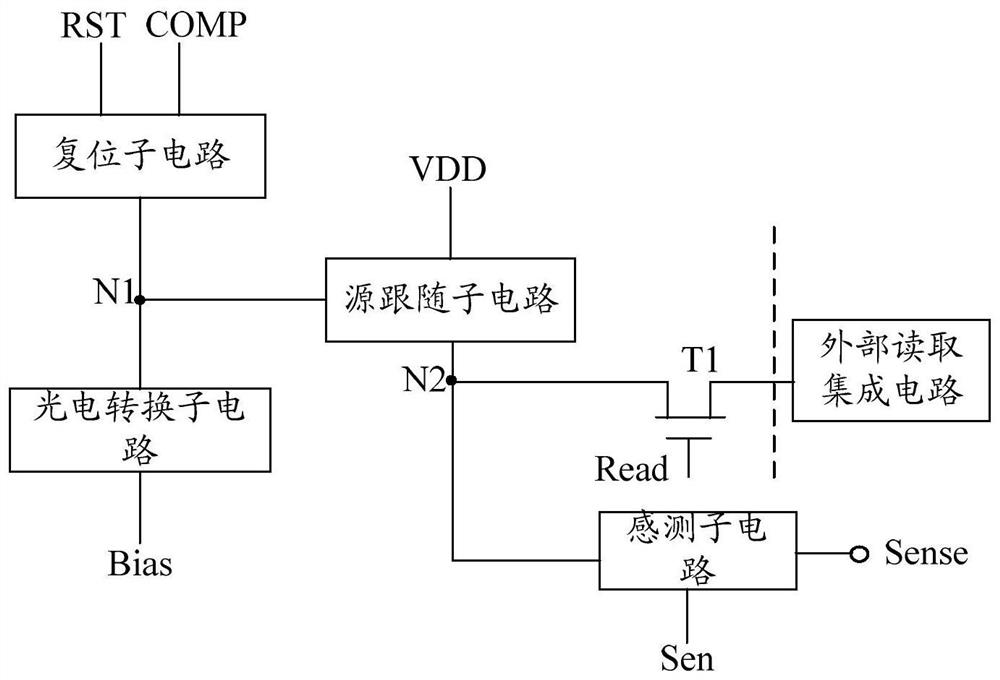
[0079] In this embodiment, the light intensity detection circuit further includes a multiplexing sub-circuit, and the multiplexing sub-circuit includes: a first transistor T1 inside the pixel unit and a multiplexer MUX outside the pixel unit. By using a multiplexer MUX, the number of transistors within a pixel cell is further reduced to maximize fill factor.

[0080] In an exemplary embodiment, Figure 9 The equivalent circuit diagram of the multiplexing sub-circuit provided for the embodiment of the present application, such as Figure 9 As shown, the multiplexing sub-circuit includes: a first transistor T1 located inside the pixel unit and a multiplexer MUX located outside the pixel unit, the sensing sub-circuit is an external sensing circuit located outside the pixel unit, and the reading The subcircuit is an external readout integrated circuit located outside the pixel unit.

[0081] Specifically, the control pole of the first transistor T1 is connected to the read contr...

no. 3 example

[0088] Based on the inventive concepts of the foregoing embodiments, the embodiments of the present application further provide a light intensity detection device, including the light intensity detection circuit described in any one of the foregoing embodiments.


PUM


Abstract

The application discloses a light intensity detection circuit, a light intensity detection method and a device. The light intensity detection circuit includes a photoelectric conversion sub-circuit, a source follower sub-circuit, a reset sub-circuit, a reading sub-circuit and a sensing sub-circuit. The circuit generates a corresponding electrical signal according to the incident light signal and outputs it to the first node; the source follower subcircuit generates a corresponding voltage or current signal according to the electrical signal of the first node and outputs it to the second node; the reading subcircuit reads the first node The voltage or current signal of the two nodes is used to determine the incident light intensity; the reset subcircuit provides the voltage of the compensation voltage terminal to the first node, and the voltage of the compensation voltage terminal includes a reference voltage and a compensation voltage, and the compensation voltage is equal to the reset voltage and the sensed second The difference between the voltages of the nodes; when the voltage of the first node is the reference voltage, the sensing subcircuit senses the voltage of the second node. The present application eliminates sensitivity differences between different pixel units caused by threshold voltage changes.

Description

technical field [0001] The present application relates to but not limited to the field of display technology, and in particular relates to a light intensity detection circuit, a light intensity detection method and a device. Background technique [0002] X-ray (X-ray) detection is widely used in medical (such as X-ray chest), non-destructive testing (such as metal flaw detection), security testing, air transportation and other fields. X-ray flat panel detectors include direct flat panel detectors and indirect flat panel detectors. Indirect flat panel detectors include charge coupled devices (Charge Coupled Device, CCD), complementary metal oxide semiconductors (Complementary Metal Oxide Semiconductor, CMOS), non Among them, amorphous silicon flat panel detectors can have a larger imaging area and lower distortion than CMOS and CCD flat panel detectors. [0003] For large area X-ray flat panel detectors, the passive pixel sensor (Passive Pixel Sensor, PPS) structure provides...

Claims


Application Information

Patent Timeline
Patent Type & Authority Patents(China)
IPC IPC(8): G01J1/16G01J1/44
CPCG01J1/16G01J1/44G01J2001/4473G01J1/18G01J1/46G01J2001/446
Inventor 钟昆璟孔德玺
Owner BOE TECH GRP CO LTD
Why Eureka
Try Eureka