Fingerprint identification display device and electronic equipment

A display device and fingerprint recognition technology, which is applied in character and pattern recognition, acquisition/organization of fingerprints/palmprints, optics, etc., can solve problems such as high cost, affecting display effect, difficult process, etc., and achieves the convenience of mass production and processing Effect

Pending Publication Date: 2020-06-26
BOE TECH GRP CO LTD +1
View PDF0 Cites 2 Cited by
  • Summary
  • Abstract
  • Description
  • Claims
  • Application Information

AI Technical Summary

Problems solved by technology

The LCD screen includes a liquid crystal display unit and a backlight unit arranged in layers. In the prior art, a silicon-based optical fingerprint sensor is arranged on the backlight side of the backlight unit. The current technology needs to dig holes in the backlight unit, which will affect the display effect, or the backlight will The unit uses a wavelength-selective transmissive membrane material. The existing membrane material is not wavelength-selective and needs to be re-developed and verified. The technology development is difficult and the effect is unknown; or, in the LCD unit Integrated glass-based optical fingerprint sensor, the process is difficult, the cost is high, and it is difficult to mass produce in a short time

Method used


Image

  • Fingerprint identification display device and electronic equipment
  • Fingerprint identification display device and electronic equipment
  • Fingerprint identification display device and electronic equipment

Examples


Embodiment Construction

[0029] The present invention will be further described in detail below with reference to the drawings and embodiments. It can be understood that the specific embodiments described here are only used to explain the related invention, but not to limit the invention. In addition, it should be noted that, for ease of description, only the parts related to the invention are shown in the drawings.

[0030] It should be noted that the embodiments of the present invention and the features in the embodiments can be combined with each other if there is no conflict. Hereinafter, the present invention will be described in detail with reference to the drawings and in conjunction with the embodiments.

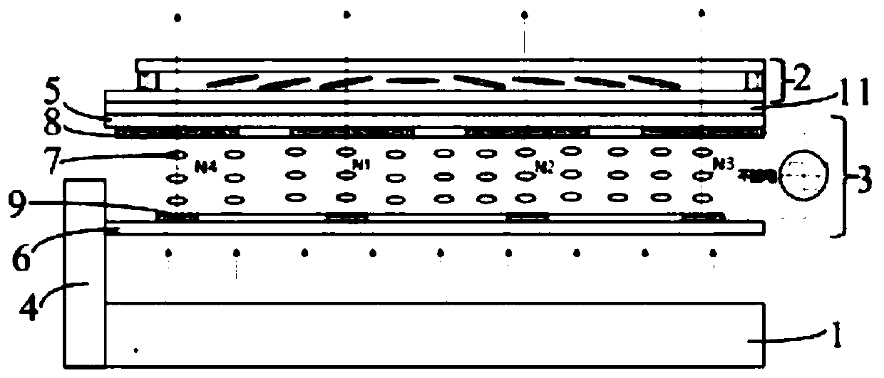
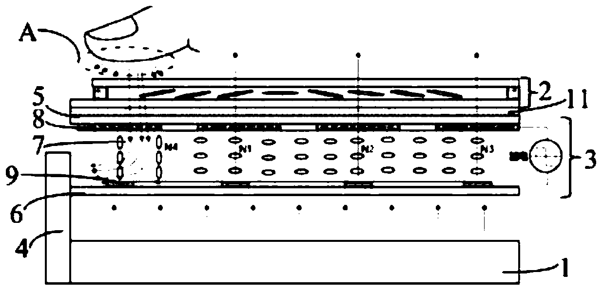
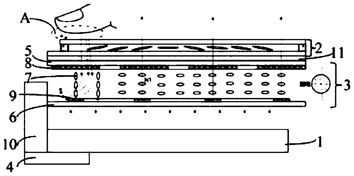
[0031] Such as figure 1 with figure 2 As shown, the fingerprint identification display device provided by the embodiment of the present invention includes a backlight unit 1 and a liquid crystal display unit 2 located on the light emitting side of the backlight unit 1, and further includes: a l...


PUM


Abstract

The invention discloses a fingerprint identification display device and electronic equipment. The fingerprint recognition display device comprises a backlight unit and a liquid crystal display screenunit arranged on a light emitting side of the backlight unit. The fingerprint recognition display device further comprises a liquid crystal lens which is arranged between the liquid crystal display screen unit and the backlight unit and used for being in a lens state when the liquid crystal display screen unit is pressed by a finger, and changing the propagation direction of reflected light of a fingerprint and an optical sensor which is used for receiving the reflected light of the finger fingerprint and performing photoelectric conversion. The propagation direction of reflected light of a fingerprint is controlled through the liquid crystal lens and thus the reflected light of finger fingerprints is emitted from the liquid crystal lens; the optical sensor receives the reflected light ofthe finger fingerprints emitted from the liquid crystal lens for fingerprint recognition; the internal structure of an existing liquid crystal display screen unit and the structure of a backlight unitare not changed, and mass production is facilitated.

Description

Technical field [0001] The present invention generally relates to the field of display technology, and in particular to a fingerprint identification display device and electronic equipment. Background technique [0002] OLED (Organic Light Emitting Diode, organic light-emitting diode) display screens can easily integrate optical fingerprint recognition systems under the OLED screen due to the advantage that they do not need a backlight. LCD (Liquid Crystal Display, liquid crystal display) needs backlight to emit light. OLED is more advanced than the under-screen fingerprint identification technology of LCD. How to integrate fingerprint identification system under LCD screen is currently a hot research topic. [0003] Fingerprint recognition mainly includes three types of recognition methods: capacitive, optical, and ultrasonic. Compared with capacitive and ultrasonic, optical fingerprint recognition technology is more mature and is more suitable for under-screen fingerprint recogni...

Claims


Application Information

Patent Timeline
Patent Type & Authority Applications(China)
IPC IPC(8): G02F1/1333G02F1/1347G02F1/1343G06K9/00
CPCG02F1/1333G02F1/1347G02F1/1343G06V40/1318
Inventor 张琦穆景飞杨胜伟郭亚军杨明刘冬杨瑞锋刘宇飞金美灵杨华旭徐俊杰
Owner BOE TECH GRP CO LTD
Why Eureka
Try Eureka