Scattering imaging device and method based on deep learning

A technology of scattering imaging and deep learning, applied in the direction of neural learning methods, optics, optical components, etc., can solve problems such as difficult to deal with dynamic or changing disordered medium environments, high requirements for optical path accuracy, and long imaging calibration time, etc., to achieve The structure is simple, the accuracy of the optical path is not high, and the imaging speed is fast

Active Publication Date: 2020-06-26
NANJING UNIV OF SCI & TECH
View PDF2 Cites 9 Cited by
  • Summary
  • Abstract
  • Description
  • Claims
  • Application Information

AI Technical Summary

Problems solved by technology

However, the above methods have their own advantages and disadvantages and applicable conditions. The imaging calibration time of the wavefront shaping method and the phase conjugation method is very long, and it is difficult to cope with the dynamic or rapidly changing disordered medium environment; the memory effect method based on the speckle correlation characteristic is facing It fails with thicker scattering media, and since it is a mesoscopic effect, it also fails when the observed object size is large
At the same time, the above methods all have extremely high requirements on the accuracy of the optical path, and the realized optical path is also relatively complicated.

Method used


Image

  • Scattering imaging device and method based on deep learning
  • Scattering imaging device and method based on deep learning
  • Scattering imaging device and method based on deep learning

Examples


Embodiment Construction

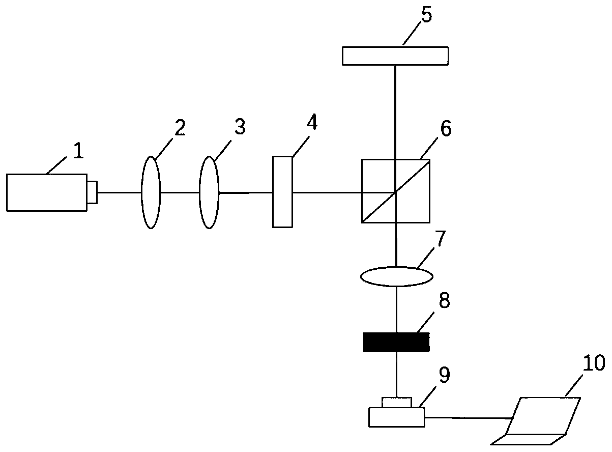
[0031] Such as figure 1 As shown, a deep learning-based scattering imaging device includes a collimated light source 1, a first lens 2, a second lens 3, a linear polarizer 4, a spatial light modulator 5, a beam splitter 6, a third lens 7, Scattering medium 8, photodetector 9, image reconstruction module 10;

[0032] The collimated light source 1, the first lens 2, the second lens 3, the linear polarizer 4, and the beam splitter 6 are sequentially arranged along the first optical axis, and the spatial light modulator 5, the third lens 7, and the scattering medium 8 , The photodetector 9 is arranged along the second optical axis, the first optical axis and the second optical axis intersect at the beam splitter 6 and the second optical axis is perpendicular to the direction of the first optical axis, wherein the scattering medium 8 is arranged on the third lens 7 on the focal plane;

[0033] The light emitted by the collimated light source 1 is beam-expanded by the first lens 2...


PUM


Abstract

The invention discloses a scattering imaging device based on deep learning. The scattering imaging device comprises a collimated light source, a first lens, a second lens, a linear polarizing film, aspatial light modulator, a beam splitter, a third lens, a scattering medium, a photoelectric detector and an image reconstruction module; the collimation light source, the first lens, the second lens,the linear polarizing film and the beam splitter are sequentially arranged along a first optical axis. The spatial light modulator, the third lens, the scattering medium and the photoelectric detector are arranged along a second optical axis, the first optical axis and the second optical axis intersect at the beam splitter, the second optical axis is perpendicular to the direction of the first optical axis, and the scattering medium is arranged on the focal plane of the third lens; and the image reconstruction module is used for reconstructing a speckle image according to the speckle information recorded by the photoelectric detector. The optical path structure is simple, the requirement for the accuracy of the optical path is not high, and the constructed neural network can automaticallycompensate for various errors existing in the optical path.

Description

technical field [0001] The invention belongs to scattering imaging technology, in particular to a deep learning-based scattering imaging device and method. Background technique [0002] Scattering media are ubiquitous in life. When the light wave propagates in the scattering medium, the disordered scattering particles inside the medium will hinder the free propagation of the light wave, and make the wave vector direction and phase of the light change randomly. Therefore, after the light wave passes through the disordered medium, it will present a random speckle pattern. These speckle patterns seem to have lost the stable distribution and correlation of the original light field, but studies have shown that the ballistic light in the speckle still retains some coherence, so there is still enough information in these speckle patterns to reconstruct image of the object. [0003] The methods to realize scattering imaging mainly include: (1) wavefront shaping method based on fe...

Claims


Application Information

Patent Timeline
Patent Type & Authority Applications(China)
IPC IPC(8): G06N3/04G06N3/08G02B27/00
CPCG06N3/08G02B27/00G06N3/045
Inventor 辛煜庄秋实
Owner NANJING UNIV OF SCI & TECH
Why Eureka
Try Eureka