
Remote-sensing image change detection method

A remote sensing image and change detection technology, which is applied in image enhancement, image analysis, image data processing, etc., can solve the problems of reducing the accuracy of change detection results, low detection accuracy, and noise sensitivity, so as to reduce the difficulty of threshold selection and overcome background information Complex, reliable results

Active Publication Date: 2020-06-26
宁波市测绘和遥感技术研究院
View PDF7 Cites 5 Cited by
  • Summary
  • Abstract
  • Description
  • Claims
  • Application Information

AI Technical Summary

Problems solved by technology

Among them, the pixel-based change detection method is based on a single pixel, and usually uses the spectral information of the pixel to directly extract the change information of remote sensing images in different phases. This type of change detection method is simple and easy to use, so it is widely used. This type of detection method only considers the characteristics of a single pixel, lacks the spectral characteristics of surrounding pixels and the spatial feature information of adjacent pixels, the detection accuracy is low, and this type of method is sensitive to noise, so it is easy to produce salt and pepper effect, which increases a lot of manual work. Workload handled, not highly automated
In addition, the object-oriented change detection method is based on image segmentation, which divides the image into several objects and then performs change detection. This type of method integrates spectral information and spatial information when performing image segmentation, which can better overcome noise. , but due to the limitations of existing segmentation algorithms, it is difficult to achieve the best segmentation for the same type of research objectives, and inaccurate or incomplete segmentation can easily lead to missed or over-detected situations, and in the process of change detection It is easy to introduce new noise and reduce the accuracy of change detection results

Method used


Image

  • Remote-sensing image change detection method
  • Remote-sensing image change detection method
  • Remote-sensing image change detection method

Examples


Embodiment Construction

[0029] The present invention will be further described in detail below in conjunction with the accompanying drawings and embodiments.

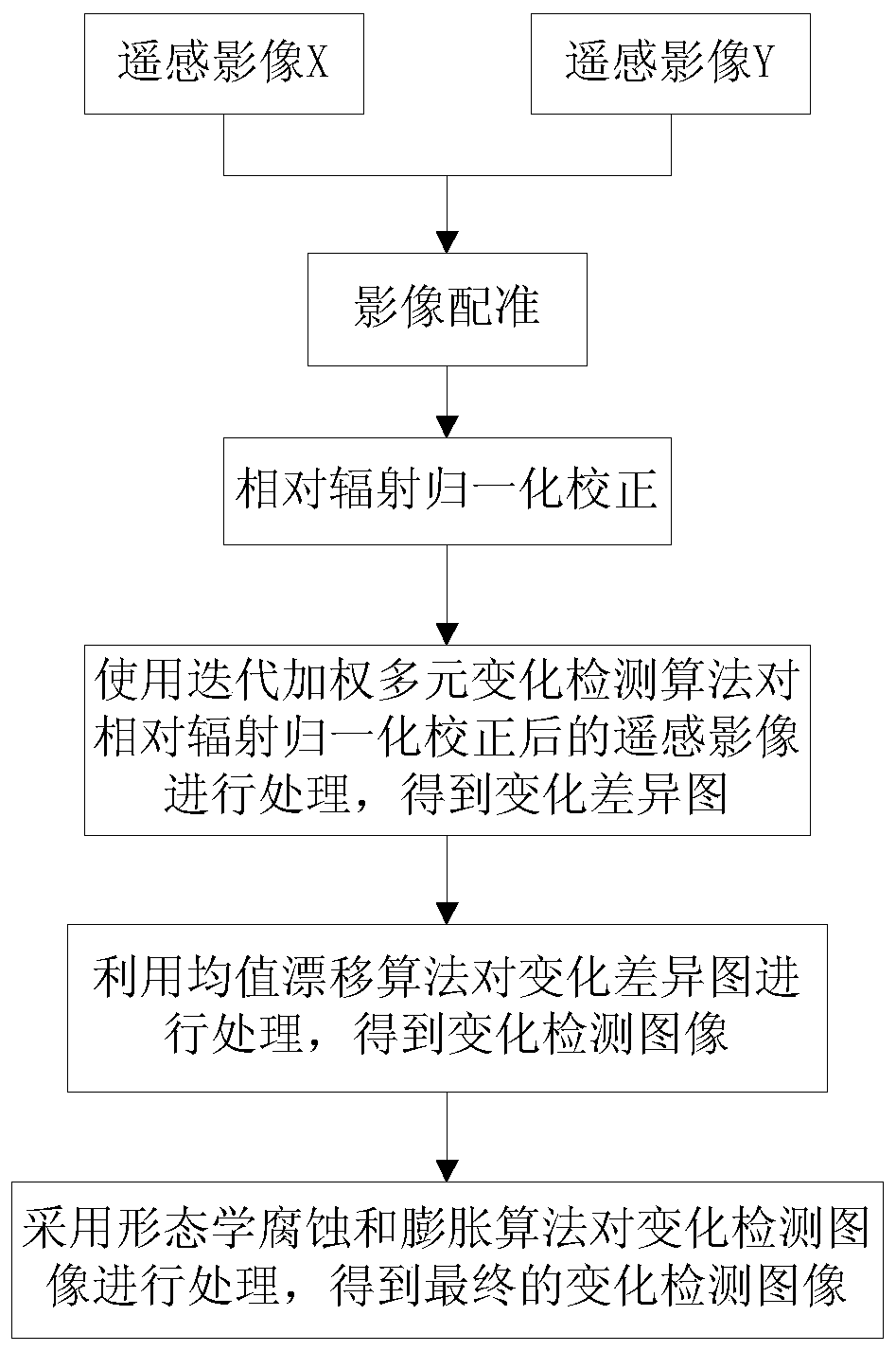
[0030] Such as figure 1 As shown, a remote sensing image change detection method includes the following steps:

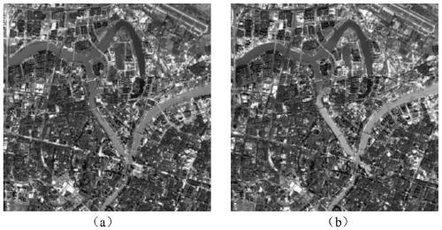
[0031] Step 1. Input two multi-spectral remote sensing images of the same area and different time phases, which are respectively recorded as remote sensing image X and remote sensing image Y; the data source used in this embodiment is as figure 2 As shown, image (a) is the remote sensing image of a certain area taken by Landsat8 satellite in 2016, image (b) is the remote sensing image of the same area as image (a) taken by the satellite in 2018, image (a) Exactly the same area as image (b);

[0032] Step 2. Perform image registration on remote sensing image X and remote sensing image Y to obtain remote sensing image X and remote sensing image Y after image registration; wherein, image registration uses conventional methods in the...


PUM


Abstract

The invention relates to a remote sensing image change detection method. The method includes: inputting two multispectral remote sensing images of the same area and different time phases; carrying outimage registration on the two remote sensing images; performing relative radiation normalization correction on the remote sensing image after image registration, determining change pixels of the reartime-phase remote sensing image after radiation normalization correction relative to the front time-phase remote sensing image by using an iterative weighted multivariate change detection algorithm,and forming a change difference graph by using all the change pixels; processing the change difference graph by using a mean shift algorithm to obtain a change detection image; and finally, adopting amorphological corrosion and expansion algorithm to process the change detection image, so as to obtain a final change detection image. According to the method, the problems of complex background information and serious noise interference of different time-phase multispectral images are solved, the threshold selection difficulty is reduced to the maximum extent, and the spiced salt effect in change detection is effectively reduced, so that the detection result is more reliable and more stable.

Description

technical field [0001] The invention relates to the technical field of remote sensing image processing, in particular to a remote sensing image change detection method. Background technique [0002] Remote sensing image change detection takes ground objects as the research object, including natural ground objects and man-made ground objects. Changes in the characteristics of ground features, such as the disappearance, appearance, and structural changes of ground features, will cause changes in remote sensing images. In addition to these factors that cause image changes, factors such as the angle of sunlight, atmospheric conditions, sensor accuracy, soil moisture conditions, and phenological cycle characteristics will more or less cause changes in remote sensing images. Such factors are usually referred to as interference. Before change detection, remote sensing images need to be preprocessed to minimize the influence of interference factors on change detection. [0003] A...

Claims


Application Information

Patent Timeline
IPC IPC(8): G06T7/00G06T7/33G06T7/13G06T7/11G06K9/62
CPCG06T7/0002G06T7/33G06T7/13G06T7/11G06T2207/10032G06F18/23
Inventor 聂倩赵艳福陈立波廖佳张伟七珂珂
Owner 宁波市测绘和遥感技术研究院
Learn More