Rotor oil-cooled permanent magnet motor

A permanent magnet motor, oil cooling technology, applied in electrical components, electromechanical devices, electric components, etc., can solve the problems of complex structure, poor cooling effect of permanent magnet rotor, and high noise of permanent magnet motor, without increasing the volume and weight, The effect of increasing complexity

Active Publication Date: 2020-06-26
WUHAN MARINE ELECTRIC PROPULSION RES INST CHINA SHIPBUILDING IND CORP NO 712 INST
View PDF4 Cites 4 Cited by
  • Summary
  • Abstract
  • Description
  • Claims
  • Application Information

AI Technical Summary

Problems solved by technology

[0005] The present invention aims at the poor cooling effect or complicated structure of the permanent magnet rotor of the existing low-speed direct drive permanent magnet motor with its own fan, and the problem

Method used


Image

  • Rotor oil-cooled permanent magnet motor
  • Rotor oil-cooled permanent magnet motor
  • Rotor oil-cooled permanent magnet motor

Examples


Embodiment 1

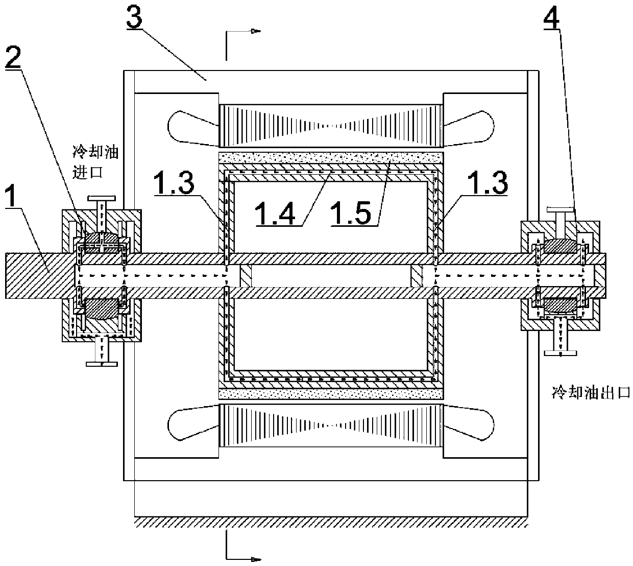
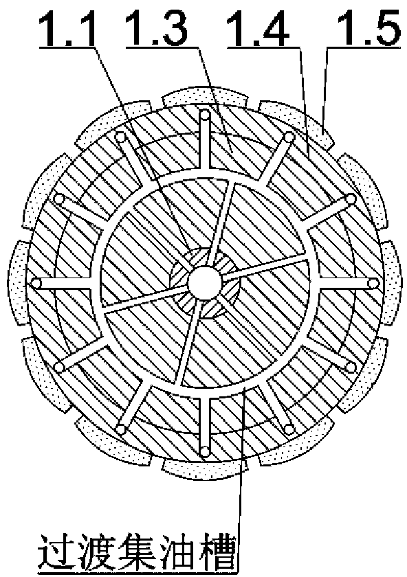
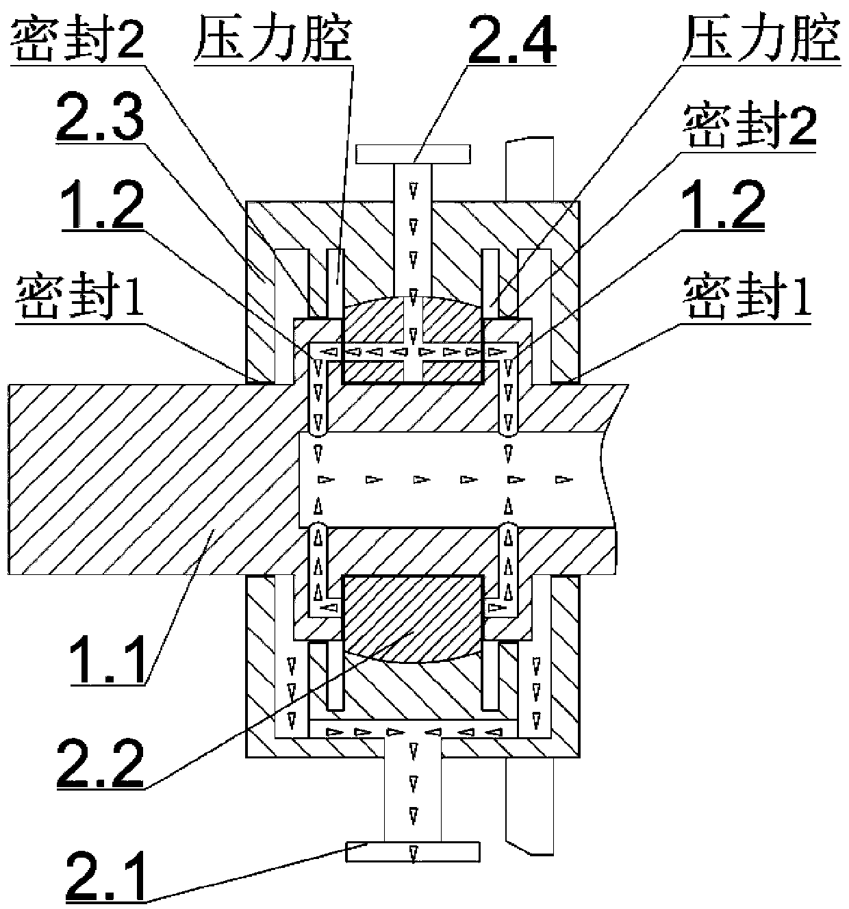
[0019] figure 1 , figure 2 Shown is a basic embodiment of the rotor oil-cooled permanent magnet motor based on the flow channel structure of the present invention. The motor consists of a stator assembly 3, a permanent magnet rotor 1 and sliding bearings on the left and right sides. The stator part is a conventional AC motor stator, and the inner rotor is a radial surface-mounted permanent magnet pole type. The permanent magnet rotor 1 includes a rotating shaft 1.1 and a rotor bracket. 1.3. The rotor yoke 1.4 and the permanent magnet pole 1.5. The driving end is equipped with a first sliding bearing 2 with thrust, and the non-driving end is equipped with a second sliding bearing 4 that only supports radially. The center hole of the rotating shaft 1.1 is filled with lubricating oil The axial flow passage of the shaft needs to be blocked according to the specific structure. The driving end of the shaft 1.1 is provided with two shaft shoulders 1.2. In order to minimize the infl...

Embodiment 2

[0029] Figure 5 Shown is a basic embodiment of the rotor oil-cooled permanent magnet motor based on the heat pipe structure of the present invention. The difference between this embodiment and Embodiment 1 lies in the pole segments of the permanent magnets of the rotor.

[0030] In this embodiment, the rotor bracket 1.3 and the rotor yoke 1.4 are respectively provided with heat pipes 1.6. The heat pipes 1.6 are connected to each other and extend to the central flow channel. The heat pipe 1.6 collects the heat of the permanent magnet pole 1.5 and transfers it to the central flow channel. The lubricating oil is taken away; the lubricating oil flow path of the heat pipe structure is short, and the lubricating oil flows in the center of the rotating shaft, which is suitable for higher speeds and has a lower demand for lubricating oil pressure.

[0031] The rotating shaft 1.1 of this embodiment can firstly process the blind hole in the center from the non-driving end, and then se...


PUM


Abstract

The invention discloses a rotor oil-cooled permanent magnet motor. The rotor oil-cooled permanent magnet motor is composed of a stator assembly, a permanent magnet rotor, a first sliding bearing and asecond sliding bearing which are arranged at the left and right sides respectively. The permanent magnet rotor comprises a rotating shaft, a rotor bracket, a rotor yoke part and a permanent magnet pole, a central runner is arranged in a central hole of the rotating shaft, and the first sliding bearing generates a lubricating oil pressure cavity to press the lubricating oil to flow through the central runner, so that the permanent magnet pole is cooled. The application object of the invention is the low-speed permanent magnet motor provided with the sliding bearings, the original lubricating oil for lubricating and cooling the sliding bearings is fully utilized, and the direct oil cooling of the permanent magnet pole is realized only by slightly improving the runners formed at the rotatingshaft and the rotor yoke part. According to the invention, the size and weight of an original motor are not increased basically, the complexity of the sliding bearings is not increased, the cooling effect is obviously superior to that of the traditional air cooling, and extra noise is not generated. According to a static pressure and dynamic pressure scheme provided by the invention, the runner and a heat pipe structure can be selected by motors with different rotating speeds.

Description

technical field [0001] The invention belongs to the technical field of motors, in particular to a rotor oil-cooled permanent magnet motor. Background technique [0002] At present, permanent magnet motors are widely used in the field of low-speed direct drive due to their advantages of high efficiency, small volume and weight, and simple maintenance. In low-speed direct drive fields such as ship electric propulsion and mining direct drive, permanent magnet motors generally use oil-lubricated sliding bearings due to low speed and high power. [0003] For permanent magnet direct drive motors in the above fields, generally the stator is an armature winding, and the rotor is a permanent magnet pole. The stator generally adopts a water-cooled structure, and the temperature resistance level of the stator insulation can reach 180°C or even higher, so the cooling of the stator is relatively easy. Although the heat generated by the permanent magnet rotor itself is small, it is diff...

Claims


Application Information

Patent Timeline
IPC IPC(8): H02K5/167H02K9/193H02K1/32
CPCH02K1/32H02K5/1672H02K9/193
Inventor 张立春张松
Owner WUHAN MARINE ELECTRIC PROPULSION RES INST CHINA SHIPBUILDING IND CORP NO 712 INST
Why Eureka
Try Eureka