
Metal debris treatment device for machining

A metal scrap and processing device technology, applied in metal processing equipment, metal processing mechanical parts, manufacturing tools, etc., can solve the problems of large labor, inconvenient operation, loose structure, etc., and achieve high processing efficiency, convenient operation, labor small amount of effect

Inactive Publication Date: 2020-06-30
江丽平
View PDF8 Cites 2 Cited by
  • Summary
  • Abstract
  • Description
  • Claims
  • Application Information

AI Technical Summary

Problems solved by technology

[0002] Metal processing debris refers to the leftovers and debris generated during the metal processing process, which is a type of scrap metal. This type of material has a loose structure, large volume, light weight, low recycling price, and is inconvenient to collect and transport. , the loss of direct smelting is high and the yield is low. Therefore, we need to compress these scraps
[0003] A Chinese patent discloses a steel scrap baler (authorized announcement number CN101259760A). This patented technology can realize three-dimensional extrusion and packaging of scrap steel, automatically cut excess feed and irregular scrap steel, and has a high degree of automation, high efficiency and safety. Well, it is mainly used in the field of scrap steel processing, but its operation is inconvenient, and its volume is large, and it cannot quickly push out the compressed metal block, which leads to a large amount of labor

Method used


Image

  • Metal debris treatment device for machining
  • Metal debris treatment device for machining
  • Metal debris treatment device for machining

Examples


Embodiment Construction

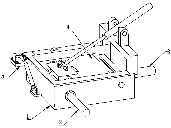
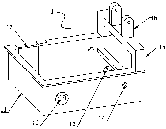
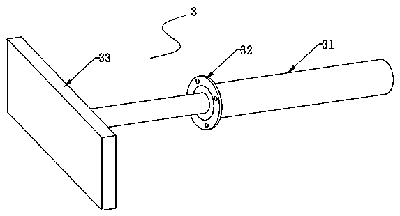
[0022] see Figure 1~5 , in an embodiment of the present invention, a metal scrap processing device for mechanical processing includes a compression box 1, a turning mechanism 5 is installed on one side of the compression box 1, and a vertical Compression mechanism 3, the front end of compression box 1 is embedded with transverse compression mechanism 2, and the inner side of the upper end of compression box 1 is connected with sealing mechanism 4, and compression box 1 includes box body 11, and one end of the inside of box body 11 is provided with second Mounting holes 13, the front and rear sides of the casing 11 are provided with shaft holes 14 near the end of the second mounting holes 13, and the top of the casing 11 is fixedly connected with a door frame 15 near the other side of the second mounting holes 13, and the casing 11 There is a first installation hole 12 on the side away from the second installation hole 13 at the front end of the box body 11, and a flip card sl...


PUM


Abstract

The invention relates to the technical on-site of metal machining, and discloses a metal debris treatment device for machining. The metal debris treatment device for machining comprises a compressionbox. An overturning mechanism is mounted on one side of the compression box. A vertical compression mechanism is embedded in the other side of the compression box. A transverse compression mechanism is embedded in the front end of the compression box. A sealing mechanism is rotationally connected to the inner side of the upper end of the compression box. According to the metal debris treatment device for machining, a sealing plate is driven by a sealing hydraulic cylinder of the sealing mechanism to rotate, and the metal debris can be arranged in the compression box in a press-fit manner; themetal debris can be compressed to an overturning plate of the overturning mechanism through mutual cooperation of the vertical compression mechanism and the transverse compression mechanism, the overturning plate is driven to rotate through an overturning hydraulic cylinder of the overturning mechanism, a compressed metal pressing block can be directly overturned out of the compression box, the next metal pressing block can be manufactured conveniently, the operation is convenient, the size of the equipment is small, the labor amount of a user is small, and the machining efficiency is high.

Description

technical field [0001] The invention relates to the technical field of metal processing, in particular to a metal scrap processing device for machining. Background technique [0002] Metal processing debris refers to the leftovers and debris generated during the metal processing process, which is a type of scrap metal. This type of material has a loose structure, large volume, light weight, low recycling price, and is inconvenient to collect and transport. , The loss of direct smelting is high and the yield is low. Therefore, we need to compress these scraps. [0003] A Chinese patent discloses a steel scrap baler (authorized announcement number CN101259760A). This patented technology can realize three-dimensional extrusion and packaging of scrap steel, automatically cut excess feed and irregular scrap steel, and has a high degree of automation, high efficiency and safety. Well, it is mainly used in the field of scrap steel processing, but it is inconvenient to operate, and...

Claims


Application Information

Patent Timeline
IPC IPC(8): B23Q11/00
CPCB23Q11/0042
Inventor 江丽平
Owner 江丽平
Learn More