Eureka AIR delivers breakthrough ideas for toughest innovation challenges, trusted by R&D personnel around the world.

Cell divided ice storage tank

An ice storage tank and fractal technology, applied in space heating and ventilation, heating methods, lighting and heating equipment, etc., can solve problems such as large temperature gradient, low thermal conductivity, and increased energy loss in the process of cold storage and cooling

Active Publication Date: 2020-06-30
SOUTHEAST UNIV
View PDF14 Cites 1 Cited by
  • Summary
  • Abstract
  • Description
  • Claims
  • Application Information

AI Technical Summary

Problems solved by technology

As a cold storage medium, ice has a large latent heat of phase change, stable performance, low cost, large quantity and easy availability, no pollution, and a basically constant phase change temperature. , which increases the energy loss in the cold storage and cooling process, so in order to improve the thermal conductivity of the ice storage tank and improve the energy utilization efficiency of the ice storage tank, it is urgent to find a new type of high-efficiency heat conduction enhanced ice storage tank

Method used


Image

  • Cell divided ice storage tank
  • Cell divided ice storage tank
  • Cell divided ice storage tank

Examples


Embodiment Construction

[0026] Below in conjunction with accompanying drawing for further description:

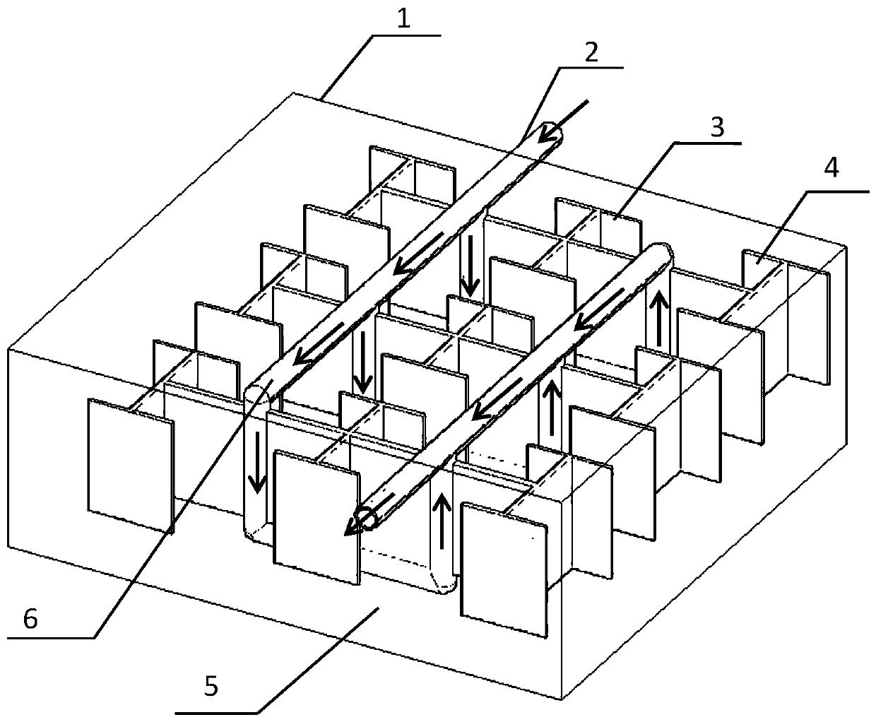
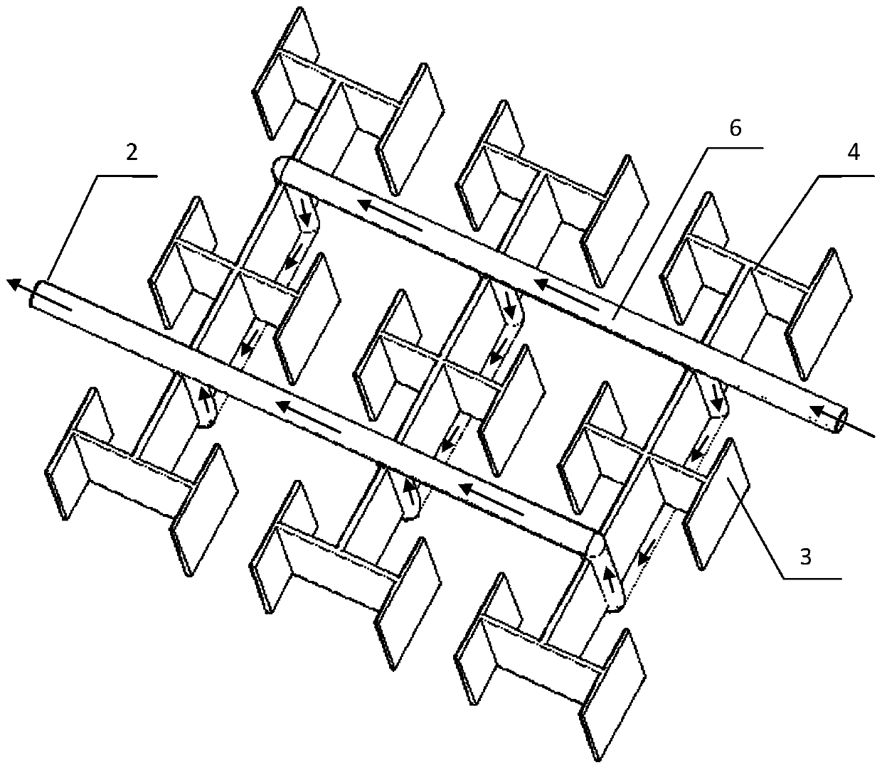
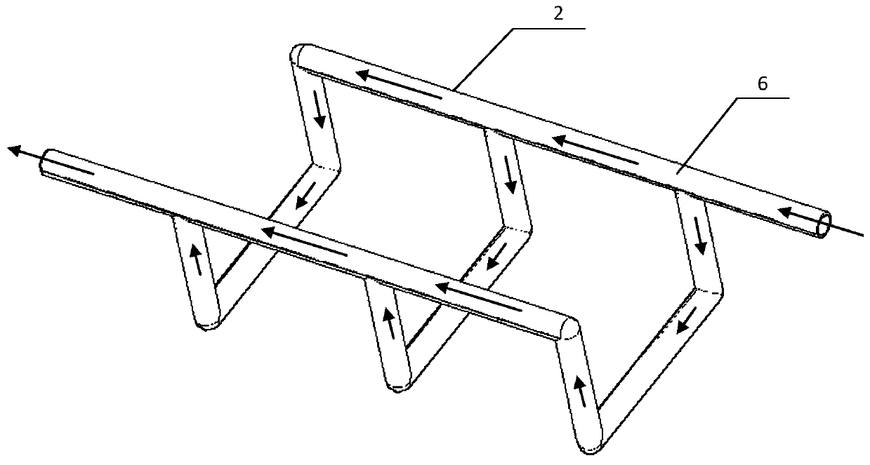
[0027] figure 1 An overall schematic diagram of the compartment fractal ice storage tank of the present invention is given. It is composed of tank body 1, coil pipe 2, thermal diffusion plates 3 and 4, cold storage medium 5 and brine 6. In order to reduce the loss of cooling capacity, the wall surface of the tank body 1 is sandwiched with thermal insulation material and wrapped with thick polystyrene boards. The coil tube 2 is arranged in the tank body 1, and the coil tube at the inlet and outlet extends out of the tank body, so that the brine 6 flows in from one end and flows out from the other end. The thermal diffusion plates 3 and 4 are arranged on the vertical coil tube, and the cold storage medium 5 placed in the tank. In order to facilitate observation and understanding, figure 2 A three-dimensional diagram of the internal structure of the ice storage tank is given.

[0028] image 3...


PUM

PropertyMeasurementUnit
Angleaaaaaaaaaa

Abstract

The invention discloses a cell divided ice storage tank. The cell divided ice storage tank comprises a tank body and coil pipes arranged in the tank body. The coil pipes comprise a main liquid inlet pipe, a main liquid outlet pipe and connecting pipes connected between the main liquid inlet pipe and the main liquid outlet pipe. The connecting pipes comprise vertical coil pipes arranged on the mainliquid inlet pipe and the main liquid outlet pipe in a spaced manner and horizontal coil pipes which connect adjacent two vertical coil pipes in the horizontal direction. Heat diffusing plates are arranged on the vertical coil pipes, the heat diffusing plates are equivalent to the vertical coil pipes in height, and the heat diffusing plates are of cell divided structures which are paved towards the inside and the outside based on the vertical coil pipes in the horizontal direction. According to the cell divided ice storage tank, the structural compactness of the ice storage tank is improved,the transfer mode of heat can be improved effectively, heat is conducted in the optimal path from a point to a body, the heat conduction distance is shortened greatly, the heat loss is reduced and theheat exchange performance is intensified, so that purposes of efficient heat exchange and energy conservation are further achieved.

Description

technical field [0001] The invention relates to an ice storage tank, in particular to an ice storage tank with compartmental fractal structure and phase-change microcapsule fluid refrigerant which is designed to improve heat exchange performance and enhance ice storage capacity. Background technique [0002] With the increasing use of air conditioners in summer, energy shortages and power supply shortages often occur. Develop cold storage technology and use the difference in peak and valley electricity prices to realize cold storage at night and use it during the day, thereby reducing the pressure on the power grid when the air conditioner is in use, and achieving the purpose of energy saving and power saving. [0003] Ice coil ice storage tank is a widely used cold storage device. It is an ice storage device with a heat exchange surface formed by a coil immersed in the water tank. During the cold storage process, the brine or refrigerant is in the coil. Circulation, absorb...

Claims


Application Information

Patent Timeline
IPC IPC(8): F24F5/00F25D3/02
CPCF24F5/0017F25D3/02Y02E60/14
Inventor 陈永平戴俏波王贺邓梓龙
Owner SOUTHEAST UNIV
Why Eureka
Eureka Blog
Learn More