
3D gradient spin echo imaging method and device for oscillation gradient preparation

A technology of spin echo, imaging method, applied in the direction of measuring magnetic variables, measuring devices, instruments, etc.

Active Publication Date: 2020-06-30
ZHEJIANG UNIV
View PDF4 Cites 4 Cited by
  • Summary
  • Abstract
  • Description
  • Claims
  • Application Information

AI Technical Summary

Problems solved by technology

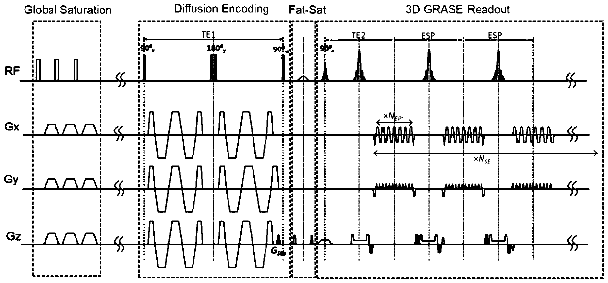
[0004] In order to overcome the deficiencies in the existing sequences, the present invention proposes a 3D gradient spin echo sequence (OGprep-GRASE) prepared by oscillating gradients to solve the problems of the two OG-dMRI sequences mentioned above and improve dMRI imaging performance

Method used


Image

  • 3D gradient spin echo imaging method and device for oscillation gradient preparation
  • 3D gradient spin echo imaging method and device for oscillation gradient preparation
  • 3D gradient spin echo imaging method and device for oscillation gradient preparation

Examples


Embodiment

[0049] The above-mentioned gradient spin echo sequence method prepared by 3D oscillatory gradient was tested on 7 healthy young male volunteers, and the specific parameters here are described below: Siemens Prisma 3.0T scanner was used for the MRI scan, and all scans All were performed with a 64-channel head coil at a maximum gradient of 80 mT / m. In this example, two sets of experiments were carried out.

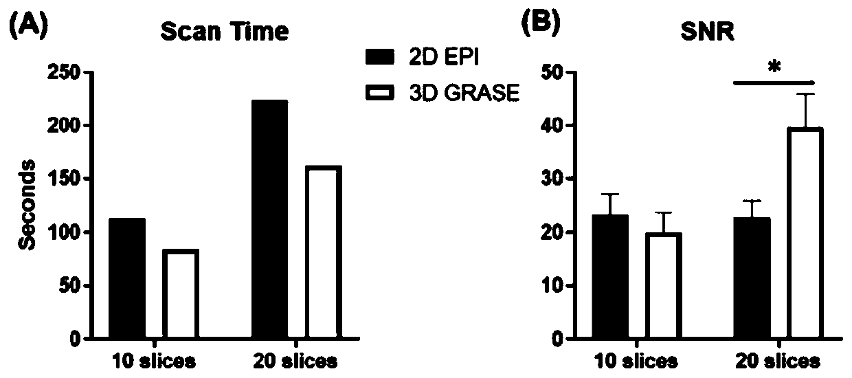
[0050] Experiment 1: In order to compare the scanning time and image signal-to-noise ratio of 3D OGprep-GRASE and 2D OG-EPI sequences, with an oscillation gradient of 50Hz, b=500s / mm 2 , 12 directions, 2 repetitions, FOV = 220×220mm, resolution 2.75×2.75mm 2 , slice thickness is 3mm (3D GRASE is 2.75×2.75×3mm 3 ) to perform an OG-dMRI scan using the following protocol:

[0051] (1) Single-shot GRASE readout sequence, N EPI =80,N SE =10, turbo factor=12, EPI factor=63, slice oversampling=20%, partial Fourier factor=61%, bandwidth=2,500Hz, TE1 / TE2 / TR=124 / 33.6 / 3000ms, scan...


PUM


Abstract

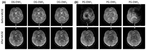
The invention discloses a 3D gradient spin echo imaging method and device for oscillation gradient preparation. The imaging method comprises the following steps: firstly, destroying previous residualtransverse magnetization in a global saturation module; secondly, embedding a pair of trapezoidal cosine oscillation gradients into a 90 degrees <x>- 180 degrees <y>- 90 degrees <-x> radio frequency pulse through a diffusion coding module, and separating diffusion coding from signal acquisition; then, using a fat saturation module\ for inhibiting the fat signal; and finally, acquiring signals in agradient spin echo reading mode, and using multiplexing sensitivity coding for reconstructing and correcting phase errors among multiple excitations. Compared with an oscillation gradient dispersionsequence based on 2D plane echo used on a 3T clinical system, the gradient spin echo sequence prepared by 3D oscillation gradient effectively improves the imaging time and the signal to noise ratio, and is beneficial to clinical conversion of a time-dependent dispersion MRI technology.

Description

technical field [0001] The present application relates to the field of magnetic resonance technology, in particular to the field of diffusion magnetic resonance imaging. Background technique [0002] Diffusion MRI (dMRI) can detect the microstructure of biological tissue according to the limited diffusion of water molecules in the microstructure environment. By changing the diffusion coding scheme, multidimensional dMRI signals can be acquired, and the signal intensity depends not only on the direction of diffusion and the b value, but also on the diffusion time and relaxation time. Specifically, diffusion time determines the sensitivity of dMRI to microstructural features at different spatial scales. The time dependence of water molecule diffusion can be obtained by measuring the dMRI signal at different diffusion times, and the time dependence curve reflects important microstructural properties such as cell size, intracellular fraction, surface area to volume ratio, etc. ...

Claims


Application Information

Patent Timeline
Patent Type & Authority Applications(China)
IPC IPC(8): G01R33/561G01R33/563
CPCG01R33/5615G01R33/5619G01R33/56341G01R33/5618G01R33/4826G01R33/4835G01R33/5611G01R33/5616
Inventor 吴丹徐义程李浩天张祎孙毅
Owner ZHEJIANG UNIV
Learn More