A fully automatic assembly and welding process for led lamp beads

A technology of LED lamp beads and LED lamps, which is applied in welding equipment, welding/welding/cutting items, manufacturing tools, etc. It can solve problems such as insufficient precision, inaccurate positioning of artificial electric switches, partial welding, etc., and improve assembly quality and efficiency, good market application value, and the effect of reducing manual operations

Active Publication Date: 2021-06-01
JIANGMEN CITY SEC LEE DI PHOTOELECTRIC LIGHTING CO LTD
View PDF7 Cites 0 Cited by
  • Summary
  • Abstract
  • Description
  • Claims
  • Application Information

AI Technical Summary

Problems solved by technology

[0003] The wide application of LED light strips has made people have higher and higher requirements for the quality of light strips. Traditional product welding is mainly carried out through manual electric wires. Due to the inaccurate positioning of manual electric wires, welding thickness and uniformity, it is easy to appear. Welding leakage and partial welding cause weak welding and even the product falls off directly, making the quality of LED light strips generally poor; and manual welding is costly and inefficient, which is not conducive to mass production. The LED light strips currently on the market Welding can only simply weld the light strips, and cannot realize an automated production line, and the precision is not high enough

Method used


Image

  • A fully automatic assembly and welding process for led lamp beads
  • A fully automatic assembly and welding process for led lamp beads
  • A fully automatic assembly and welding process for led lamp beads

Examples


Embodiment Construction

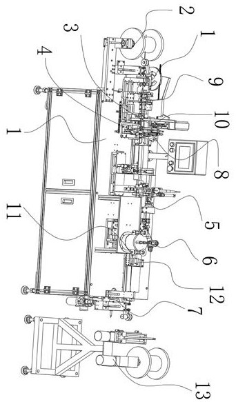
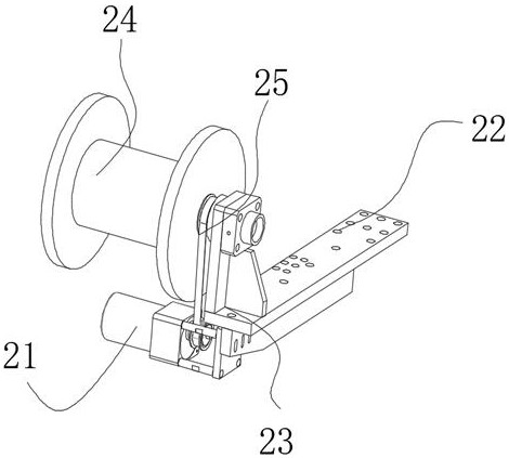
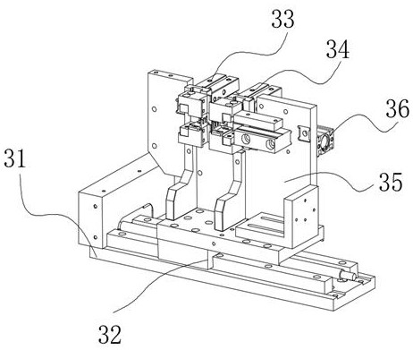
[0053] In order to facilitate the understanding of the present invention, the present invention will be described in more detail below in conjunction with the accompanying drawings and specific embodiments. Preferred embodiments of the invention are shown in the accompanying drawings. However, the present invention can be implemented in many different forms and is not limited to the embodiments described in this specification. On the contrary, these embodiments are provided to make the understanding of the disclosure of the present invention more thorough and comprehensive.

[0054] It should be noted that when an element is referred to as being “fixed” to another element, it can be directly on the other element or there can also be an intervening element. When an element is referred to as being "connected to" another element, it can be directly connected to the other element or intervening elements may also be present. The terms "fixed", "integrated", "left", "right" and si...


PUM


Abstract

The invention discloses a fully automatic assembly and welding process of LED lamp beads. The assembly process is as follows: step S1, feeding and conveying process of accessory lamp strips; step S2, process of stripping, positioning and separating the accessory lamp strips; step S3, feeding of accessory LED lamps The conveying process; step S4, the process of picking up and transferring the manipulator to the turning mechanism; step S5, the process of picking up, transferring and turning the LED light that has been turned over by the manipulator, and entering the light installation process; step S6, the process of combining the accessory LED light and the light strip to form a light strip; step S7, pairing The self-assembled light strips are soldered; step S8, dispensing the soldered light strips; step S9, performing ultraviolet positioning and curing on the glue-dispensed light strips; step S10, curing and positioning the light strips Carry out the wire-releasing and tensioning process; step S11, wind and take-up the assembled light strip; the present invention realizes automatic assembly of LED light strips, improves production efficiency and quality, and has good market application value.

Description

technical field [0001] The invention relates to the field of lamp bead assembly, in particular to a fully automatic assembly and soldering process for LED lamp beads. Background technique [0002] LED light strip refers to the assembly of LEDs on a strip-shaped FPC (flexible circuit board) or PCB hard board. It is named for its product shape like a strip. LED light strips can be divided into LED hard light strips and flexible LED light strips. The light strips have been widely used in buildings, bridges, roads, gardens, courtyards, floors, ceilings, furniture, cars, ponds, underwater, advertising, signboards, Decoration and lighting of signs, etc.; [0003] The wide application of LED light strips has made people have higher and higher requirements for the quality of light strips. Traditional product welding is mainly carried out through manual electric wires. Due to the inaccurate positioning of manual electric wires, welding thickness and uniformity, it is easy to appear....

Claims


Application Information

Patent Timeline
Patent Type & Authority Patents(China)
IPC IPC(8): B23K1/00B23P19/00B23P19/04B05D1/26B05D3/06B23K101/36
CPCB05D1/26B05D3/067B23K1/0016B23P19/001B23P19/04B23K2101/36
Inventor 吴耀均黄莉
Owner JIANGMEN CITY SEC LEE DI PHOTOELECTRIC LIGHTING CO LTD
Why Eureka
Try Eureka