
U-shaped heat exchange pipe and pipe plate welding process and application thereof

A technology for tube-sheet welding and heat-exchanging tubes, applied in welding equipment, welding accessories, manufacturing tools, etc., can solve problems such as idle waste of equipment, gap corrosion, and reduction of material tensile strength, so as to reduce production costs and overcome tube spacing Small, the effect of ensuring the tensile strength

Pending Publication Date: 2020-07-03
LUXI IND EQUIP
View PDF8 Cites 1 Cited by
  • Summary
  • Abstract
  • Description
  • Claims
  • Application Information

AI Technical Summary

Problems solved by technology

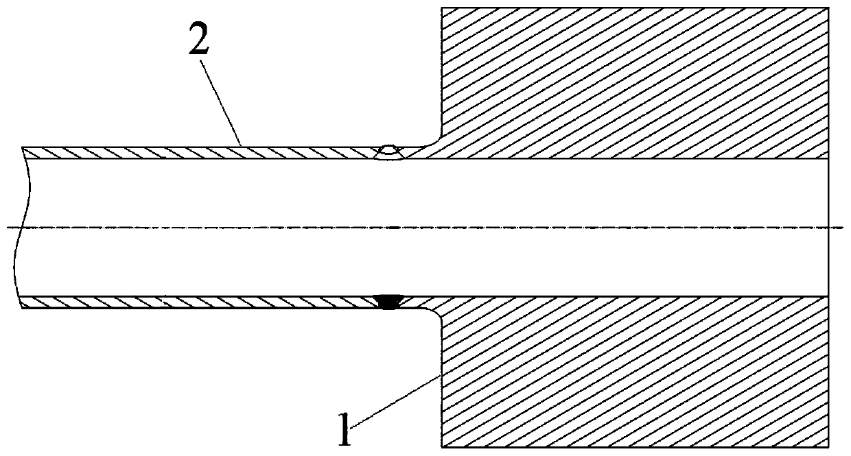
[0004] However, the inventors found that in the welding process of the heat exchange tube and the tube sheet, due to the large size of the heat exchange tube, if the inner hole welding machine is used for welding (as shown in the attached figure 1 As shown), it is necessary to purchase special welding equipment for inner hole welding, but the cost of a single inner hole welding equipment is hundreds of thousands of yuan, which is relatively high. idle waste
If the structure is changed to a fillet joint structure, due to the high temperature at this end, the tensile strength of the material is reduced, and the thickness of the fillet weld is thin, resulting in weld strength that cannot meet the requirements, and the outer wall of the heat exchange tube after welding and the tube There is a gap between the inner sides of the welding holes on the board, and the gap directly faces the working medium, which is prone to crevice corrosion

Method used


Image

  • U-shaped heat exchange pipe and pipe plate welding process and application thereof
  • U-shaped heat exchange pipe and pipe plate welding process and application thereof
  • U-shaped heat exchange pipe and pipe plate welding process and application thereof

Examples


no. 1 example

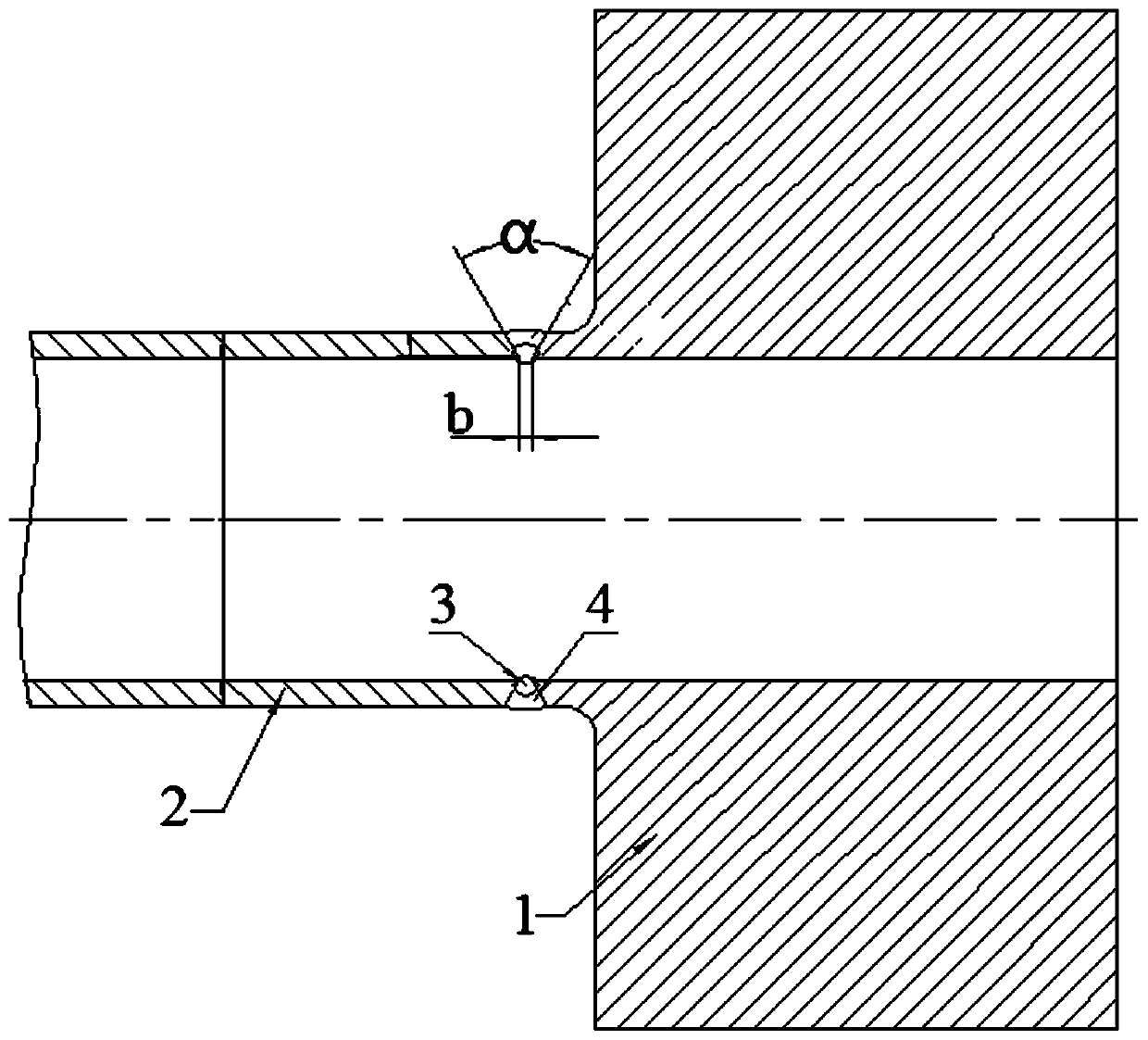
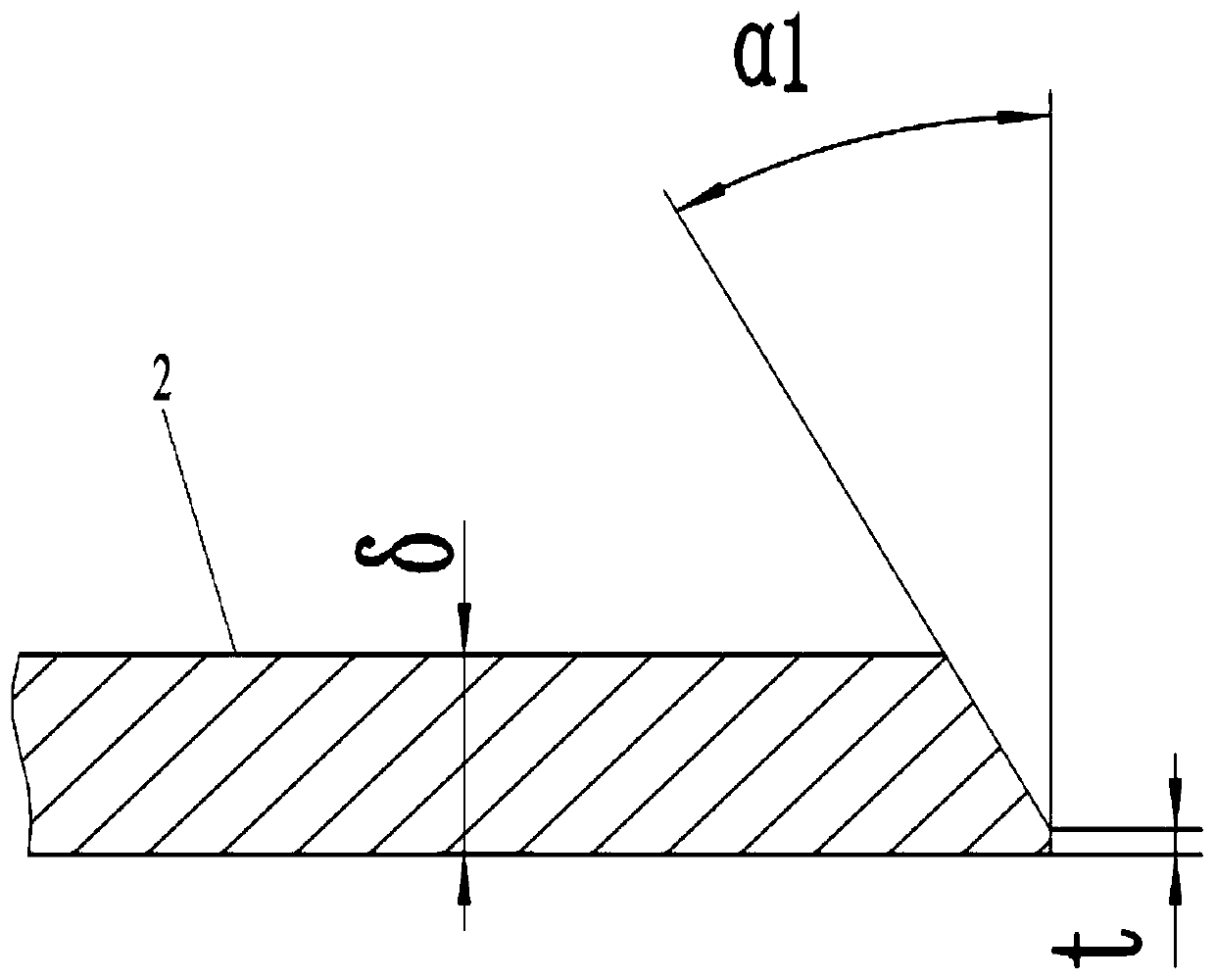
[0041] first embodiment , a U-shaped heat exchange tube and tube sheet welding process, refer to Figure 2-4 , the material of the tube sheet is 16MnⅢ forging, the thickness δ is 90mm, the material of the heat exchange tube is Q345D, and the specification is φ57×4mm, and the welding process includes the following steps:

[0042] (1) Thoroughly clean the rust and other impurities and dirt within 20mm of the welding end of the tube sheet 1 and heat exchange tube 2;

[0043] (2) Use a portable pipe beveling machine to process the convex edge of the welding hole on the tube sheet 1 and the welding end of the heat exchange tube 2 into a bevel. The mouth angle α1 is 28°.

[0044] (3) After the groove is processed, use a grinder to thoroughly clean the rust, burrs and other impurities and dirt within 20mm on both sides of the groove.

[0045] (4) After the cleaning is completed, the traditional method of threading the heat exchange tubes in columns is changed to threading the tub...

no. 2 example

[0051] second embodiment , a U-shaped heat exchange tube and tube sheet welding process, refer to Figure 2-4 , the material of the tube sheet is 16MnⅢ forging, the thickness δ is 90mm, the material of the heat exchange tube is Q345D, and the specification is φ57×4mm, and the welding process includes the following steps:

[0052] (1) Thoroughly clean the rust and other impurities and dirt within 20mm of the welding end of the tube sheet 1 and heat exchange tube 2;

[0053] (2) Use a portable pipe beveling machine to process the convex edge of the welding hole on the tube sheet 1 and the welding end of the heat exchange tube 2 into a bevel. Groove angle α1 is 25°.

[0054] (3) After the groove is processed, use a grinder to thoroughly clean the rust, burrs and other impurities and dirt within 20mm on both sides of the groove.

[0055] (4) After the cleaning is completed, the traditional method of threading the heat exchange tubes in columns is changed to threading the tubes...

no. 3 example

[0061] third embodiment , a U-shaped heat exchange tube and tube sheet welding process, refer to Figure 2-4 , the material of the tube sheet is 16MnⅢ forging, the thickness δ is 90mm, the material of the heat exchange tube is Q345D, and the specification is φ57×4mm, and the welding process includes the following steps:

[0062] (1) Thoroughly clean the rust and other impurities and dirt within 20mm of the welding end of the tube sheet 1 and heat exchange tube 2;

[0063] (2) Use a portable pipe beveling machine to process the convex edge of the welding hole on the tube sheet 1 and the welding end of the heat exchange tube 2 into a bevel. The mouth angle α1 is 30°.

[0064] (3) After the groove is processed, use a grinder to thoroughly clean the rust, burrs and other impurities and dirt within 20mm on both sides of the groove.

[0065] (4) After the cleaning is completed, the traditional method of threading the heat exchange tubes in columns is changed to threading in rows...


PUM

PropertyMeasurementUnit
angleaaaaaaaaaa

Abstract

The invention relates to the technical field of quench cooler preparation, in particular to a U-shaped heat exchange pipe and pipe plate welding process and application thereof. The U-shaped heat exchange pipe and pipe plate welding process comprises the steps of (1) groove machining; (2) groove clearing and inspection; (3) pipe penetrating of a heat exchange pipe according to rows; (4) pairing and priming coat welding; (5) priming coat detecting; (6) cover face layer welding; (7) cover face layer detecting; and (8) pressure-resistant testing. A groove in the welding part of the heat exchangepipe and a pipe plate is changed from an inner groove in an original method to a V-shaped outer groove, and is welded through manual argon arc welding instead of inner hole welding, and thus the manufacturing cost is greatly lowered. Meanwhile, in order to meet the condition that manual argon arc welding replaces inner hole welding, traditional pipe penetrating of the heat exchange pipe accordingto columns is changed to pipe penetrating of the heat exchange pipe according to rows, thus the interval between two adjacent welded junctions becomes large, thus the heat exchange pipe and the pipe plate can be welded through manual argon arc welding, and the preparation cost of a quench cooler is significantly lowered while the welding quality is guaranteed.

Description

technical field [0001] The invention relates to the technical field of quench cooler preparation, in particular to a U-shaped heat exchange tube and tube sheet welding process and its application. Background technique [0002] The information disclosed in the Background of the Invention is only intended to increase the understanding of the general background of the invention, and is not necessarily to be taken as an acknowledgment or any form of suggestion that the information constitutes the prior art that is already known to those skilled in the art. [0003] The quencher is the key equipment of the fluorine chemical project. The working temperature of the metal wall of the tube side is generally 162°C, the design temperature is 400°C, and the temperature of the working medium is 680°C (inlet) / 180°C (outlet). When the equipment is running, the inlet side pipe The average metal wall temperature of the plates is nearly 400°C. The quench cooler is a U-shaped heat exchange tu...

Claims


Application Information

Patent Timeline
Patent Type & Authority Applications(China)
IPC IPC(8): B23K9/16B23K9/32
CPCB23K9/16B23K9/32
Inventor 高希改张文明黄孝鹏张云霞白忠建张龙玲许燕芹白广斌
Owner LUXI IND EQUIP
Learn More