Rotary drawing film blowing production technology

A technology of production process and production equipment, which is applied in the field of rotary traction blown film production process, can solve the problems of easy stretching of the film, irregular edges, and uneven film roll, so as to achieve dense film roll, neat edges at both ends, and The effect of low moving speed

Active Publication Date: 2020-07-03
GUANGDONG JINMING MACHINERY
View PDF7 Cites 1 Cited by
  • Summary
  • Abstract
  • Description
  • Claims
  • Application Information

AI Technical Summary

Problems solved by technology

On the other hand, the above-mentioned twisting process belongs to the back and forth rotation, and when the special motor suddenly changes direction (commutation for short), the film is more likely to be strained
[0009] In order to reduce the degree of the above-mentioned strain or scratch, people design the second horizontal movable guide roller, the third horizontal movable guide roller, and the fourth horizontal movable guide roller as air cushion rollers. There is a fan that sends air to the air-cushion roller. When each horizontal movable guide roller is continuously twisting back and forth around the circular extrusion port, the fan continuously sends air to the air-cushion roller, so that the second horizontal movable guide roller and the third horizontal movable The surface of the guide roller and the fourth horizontal movable guide roller forms an air cushion layer. However, the angle changes continuously during the rotation and traction process, so that the tension of the film will more or less produce a component force along the axial direction of the horizontal guide roller. In addition, due to the air cushion layer, the film will continue to break away from the surface of the second horizontal movable guide roller, the third horizontal movable guide roller, and the fourth horizontal movable guide roller, so the film is easy to move along the second horizontal movable guide roller, the third horizontal movable guide roller, the fourth horizontal movable guide roller The axial direction of the horizontal movable guide roller drifts, and it has not been flattened (flattened along the axis of the guide roller), so that the final film roll is not dense and the edges are not neat (commonly known as "swing edge ")

Method used


Image

  • Rotary drawing film blowing production technology
  • Rotary drawing film blowing production technology
  • Rotary drawing film blowing production technology

Examples


Embodiment Construction

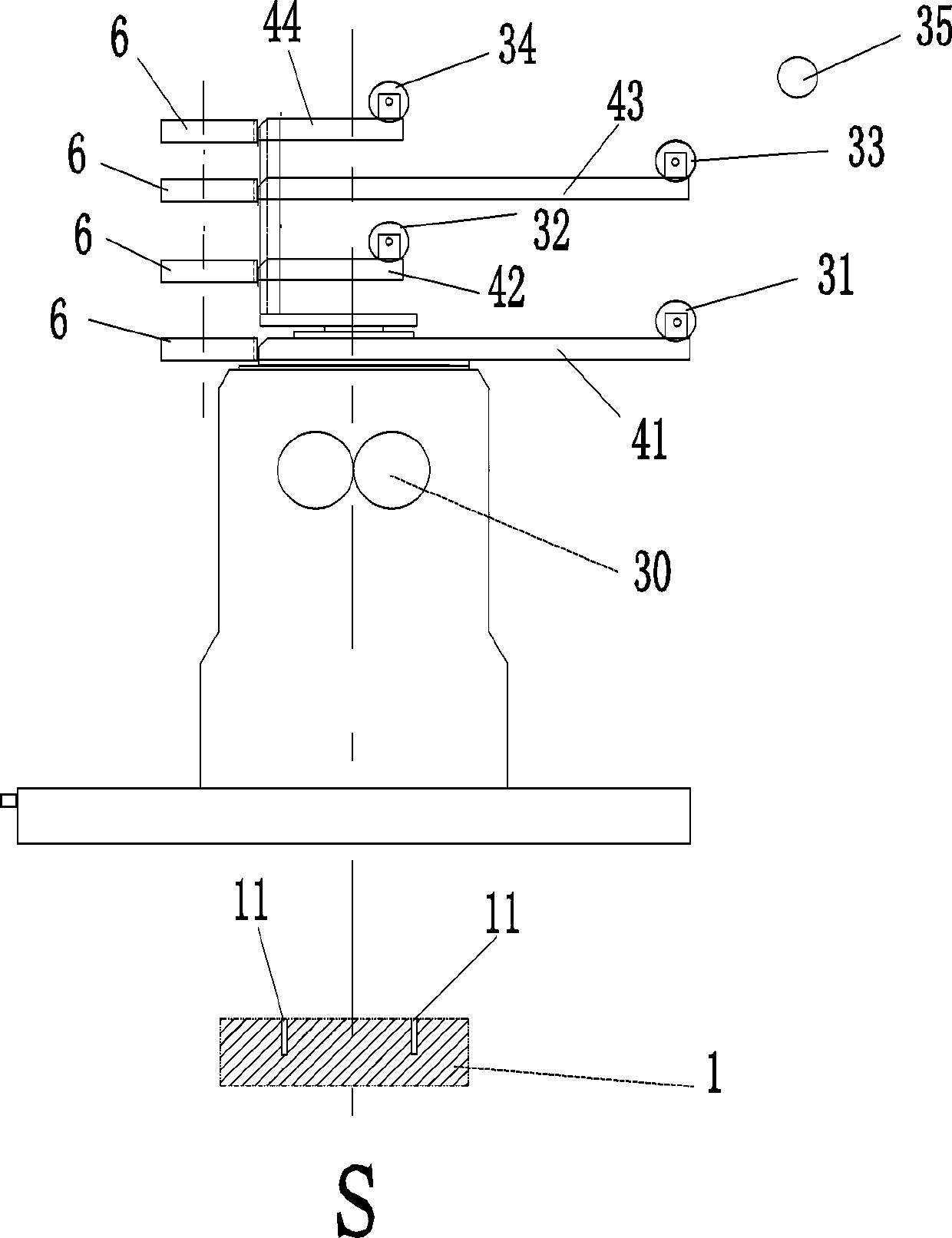
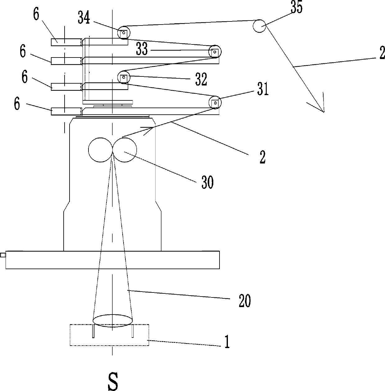
[0029] A rotary traction blown film production process, the rotary traction blown film production equipment adopted is provided with a central controller and an extrusion die head, the extrusion die head is provided with a circular extrusion port 11, and the top of the extrusion die head 11 is sequentially arranged There are traction nip rollers 30, first horizontally movable guide rollers 31, second horizontally movable guide rollers 32, third horizontally movable guide rollers 33, and fourth horizontally movable guide rollers 34, wherein the first horizontally movable guide rollers 31, the third horizontally movable guide rollers The horizontal position of the horizontal movable guide roller 33 is far away from the vertical central axis S of the annular extrusion port 11, while the horizontal positions of the second horizontal movable guide roller 32 and the fourth horizontal movable guide roller 34 are then close to the center of the circular annular extrusion port Axis S, t...


PUM


Abstract

The invention provides a rotary drawing film blowing production technology. In a rotary drawing process, the rotating speed of an either-rotation motor is gradually reduced with increase of an included angle between a central axis of a fourth horizontal moving guide roller and a reference direction, and the rotating speed of the either-rotation motor is gradually increased with reduction of an included angle value; when the included angle value is zero, the rotating speed of an either-rotation motor reaches the maximum value; and a central control unit controls output air speeds of a variable-frequency fan at all moments according to the included angle between the central axis of the fourth horizontal moving guide roller and the reference direction. According to the technology, the problems of scratching and pulling damage of a thin film can be solved, besides, a film roll obtained by final rolling is relatively compact, and the edges are relatively neat.

Description

technical field [0001] The invention belongs to the technical field of plastic film production technology, and in particular relates to a rotary traction blown film production technology. Background technique [0002] When the traditional film blowing machine is produced, the plastic raw material is melted and extruded from the circular extrusion port of the die head to form a cylindrical film bubble, and then the traction nip roll flattens the film bubble into a double-layer film, and the double-layer film bypasses The guide roller is fixed horizontally, and finally the rewinding shaft is used for rewinding. The installation direction of the horizontally fixed guide roller is parallel to the central axis of the rewinding shaft. [0003] However, due to mechanical design, mechanical structure, mechanical processing and other reasons, the thickness of each point of the cylindrical film bubble extruded from the circular extrusion port of the blown film equipment is actually di...

Claims


Application Information

Patent Timeline
Patent Type & Authority Applications(China)
IPC IPC(8): B29C48/00B29C48/355B29C48/10
CPCB29C48/0018B29C48/10B29C48/355
Inventor 陈昭楷林德坡郑武胜
Owner GUANGDONG JINMING MACHINERY
Why Eureka
Try Eureka