Drying device for air pipeline of paving material combustion test device

An air pipeline and combustion test technology, which is applied in the direction of chemical analysis, material analysis, and measuring devices by means of combustion, can solve the problems of long air compressor pipelines, air detection, and large gas consumption, so as to increase the flow distance and save energy. space, effect of increased contact

Active Publication Date: 2020-07-03
河南华豫达工程技术有限公司
View PDF16 Cites 0 Cited by
  • Summary
  • Abstract
  • Description
  • Claims
  • Application Information

AI Technical Summary

Problems solved by technology

[0002] Because the air compressor pipeline of the flooring material combustion test device is long and the air consumption is large, there is more water in the air pipeline, which is more obvious in summer and rainy days with high air humidity, and the air enters through the air pipeline. The device for the combustion experiment is to be mixed with combustible gas and burned. If there is a lot of water in the air pipeline, it will often affect the combustion temperature of the radiant panel, making it unable to meet the conditions required for the test.
Therefore, every time the equipment is ignited and pr

Method used


Image

  • Drying device for air pipeline of paving material combustion test device
  • Drying device for air pipeline of paving material combustion test device
  • Drying device for air pipeline of paving material combustion test device

Examples


Example Embodiment

[0036] Embodiment one

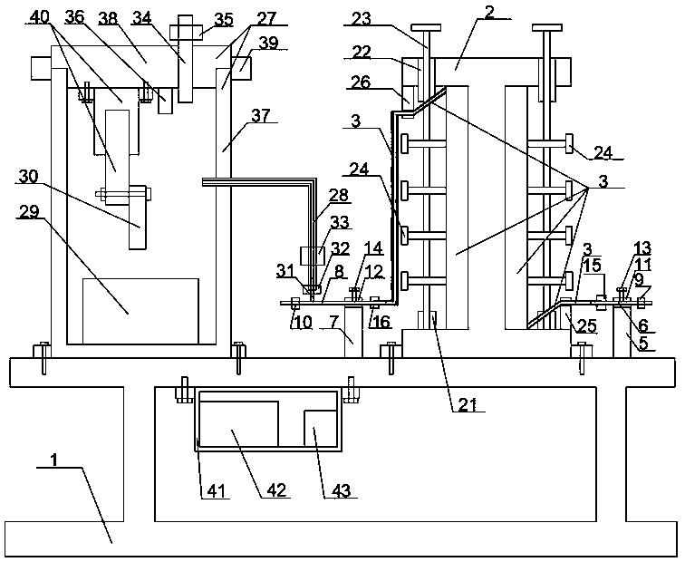
[0037] like Figure 1-7 As shown, a drying device for the air pipeline of the flooring material combustion test device, including a fixed frame 1, a drying module arranged at the right end of the fixed frame 1, and a detection module arranged at the left end of the fixed frame 1 and connected to the drying module ;

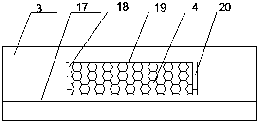
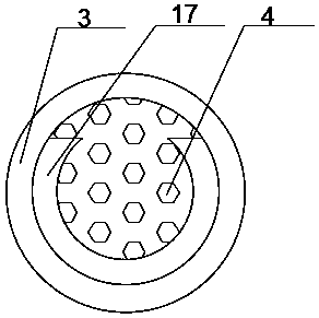
[0038] The drying module includes a wheel 2 arranged at the top right end of the fixed frame 1, an air duct 3 wound on the wheel 2, a desiccant 4 arranged in the air duct 3, and a top right end arranged at the top of the fixed frame 1 and located at The first mounting frame 5 on the right side of the wheel disc 2, the air intake pipe 6 arranged in the first mounting frame 5, the second mounting frame 7 arranged at the top right end of the fixed frame 1 and positioned at the left side of the wheel disc 2, and the second mounting frame 7 arranged on the left side of the wheel disc 2. The air outlet pipe 8 in the second installation frame 7;...

Example Embodiment

[0073] Embodiment two

[0074] The difference between this embodiment and Embodiment 1 is that: the first valve switch 9 , the second valve switch 10 , the third valve switch 33 , and the fourth valve switch 35 are all one-way valve switches.

[0075] Through the first valve switch 9, the air can only flow from the air intake pipe 6 to the air guide pipe 3, but cannot flow from the air guide pipe 3 to the air intake pipe 6, thereby preventing the dried air from being re-humidified;

[0076] Through the second valve switch 10, the air produced by the air compressor can only flow from the air outlet pipe 8 to the flooring material combustion experimental device, and cannot flow in the opposite direction, thereby avoiding the dried air from being re-wetted or polluted;

[0077] Through the third valve switch 33, the dried air can only flow from the air outlet pipe 8 to the exhaust branch pipe 31 and then to the extension pipe 28, and cannot flow in the opposite direction, thereby p...


PUM


Abstract

The invention provides a drying device for an air pipeline of a paving material combustion test device. The drying device comprises a fixing frame, a drying module arranged at the right end of the fixing frame and a detection module arranged at the left end of the fixing frame and connected with the drying module. The drying module comprises a wheel disc arranged at the right end of the top of thefixing frame, an air guide pipe wound on the wheel disc, a drying agent arranged in the air guide pipe, a first mounting frame arranged at the right end of the top of the fixing frame and located onthe right side of the wheel disc, and an air inlet pipe arranged in the first mounting frame. Through the drying device for an air pipeline of a paving material combustion test device, the air pipeline can be dried, so that the influence of accumulated water in the pipeline on the result of a combustion experiment is avoided, the working difficulty and the workload of workers can be reduced, and in addition, the drying degree of dried air can be detected and judged, so that a user can discover that the air drying effect does not reach the standard in time.

Description

technical field [0001] The invention relates to the technical field of air pipeline drying, in particular to a drying device for the air pipeline of a floor material combustion test device. Background technique [0002] Because the air compressor pipeline of the flooring material combustion test device is long and the air consumption is large, there is more water in the air pipeline, which is more obvious in summer and rainy days with high air humidity, and the air enters through the air pipeline. The device for the combustion experiment is to be mixed with combustible gas for combustion. If there is a lot of water in the air pipeline, it will often affect the combustion temperature of the radiant panel, making it unable to meet the conditions required for the test. Therefore, every time the equipment is ignited and preheated, the test personnel have to manually open the air pipe joint to drain water. In this way, although the influence of water accumulation in the pipe can ...

Claims


Application Information

Patent Timeline
IPC IPC(8): G01N31/12G01N33/00B01D53/26
CPCG01N31/12G01N33/0004B01D53/26
Inventor 梁志宏冯照剑胡冰
Owner 河南华豫达工程技术有限公司
Why Eureka
Try Eureka