Auxiliary transformer for electric locomotive and assembly process thereof
A technology for auxiliary transformers and electric locomotives, applied in the field of transformers, can solve the problems of poor anti-shock and anti-vibration performance of auxiliary transformers, and achieve the effects of saving raw materials, accurate positioning and clamping, and exquisite structure
- Summary
- Abstract
- Description
- Claims
- Application Information
AI Technical Summary
Problems solved by technology
Method used
Image

Examples
Embodiment 1
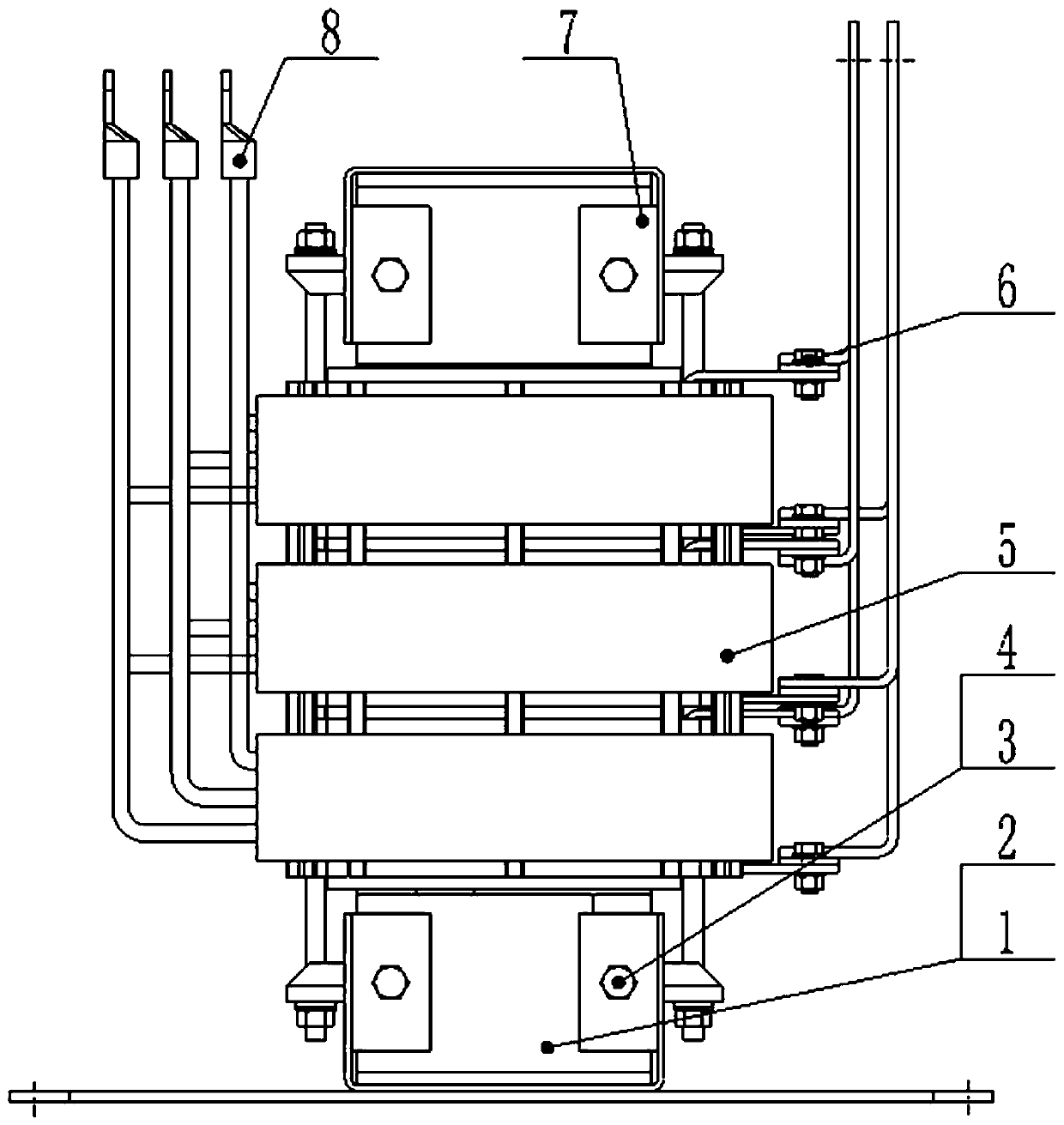
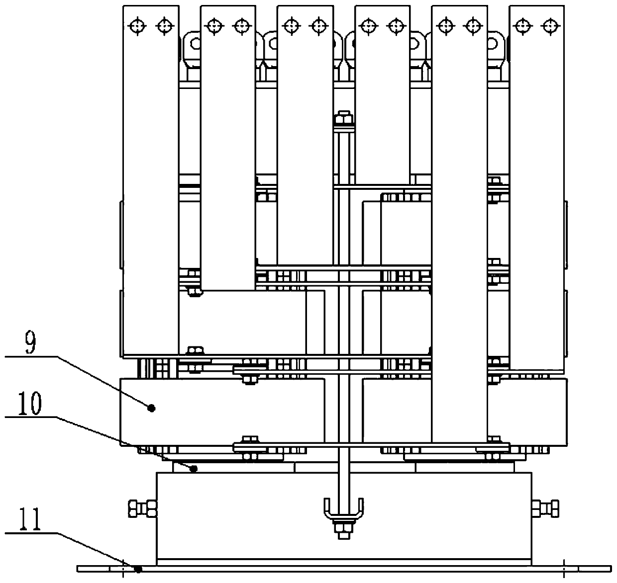
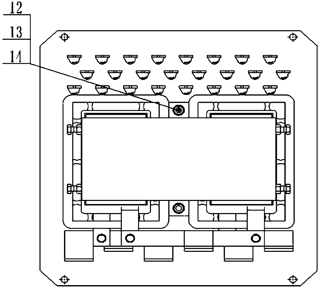
[0026] An auxiliary transformer for an electric locomotive, comprising a magnetic core 1, a coil 5 and a coil stay 9, the inner side of the coil 5 is provided with a coil stay 9, the connection of the coil stay 9 is provided with a primary terminal 8, A conductive bar 6 is provided at the inner connection of the primary terminal 8, and the outer side of the coil 5 is fixed by a hexagonal bolt 3, and the coil 5 and the hexagonal bolt 3 are fixed by a hexagonal nut 4, and the hexagonal bolt 3 is fixed with a The pressing plate 2 is provided with a magnetic core 1 in the middle of the pressing plate 2 , and a magnetic core side plate 10 is provided on the left side of the magnetic core 1 , and the magnetic core side plate 10 is fixed on the bottom plate 11 . The coil 5 is composed of a tooth bar 12, a flat washer 13 and a spring washer 14, which are arranged sequentially from inside to outside. The conductive row 6 is wound on both ends of the primary interlayer insulation 17, th...
Embodiment 2
[0032] An assembly process for an auxiliary transformer for an electric locomotive, comprising the following steps:
[0033] 1) Connect the rheostats between the transformers in series, then inject reverse current, and adopt 45° joints for the iron core model. The iron core is a silicon steel sheet core, and the silicon steel sheet iron core is 0.1 ultra-thin silicon steel sheet. Two pieces, three steps, 7mm overlapping stacking;
[0034] 2) Select the metal conductor to be set on the cutting coil leakage flux magnetic force line, use the mold to tightly wind the transformer coil, use the tinned copper conductive bar to rivet the wire ends together, and finally perforate and electroplate the coil into strips;
[0035] 3) The magnetic core adopts a multi-strand wire structure, the coil is shielded and the insulating layer is covered. The internal conductive connector passes through the insulating substrate adjacent to the inner circumference of the magnetic core, and its extern...
Embodiment 3
[0037] An assembly process for an auxiliary transformer for an electric locomotive, comprising the following steps:
[0038] 1) Connect the varistors between the transformers in series, then inject reverse current, and use 60° joints for the iron core model. The iron core is a silicon steel sheet core, and the silicon steel sheet iron core is 0.1 ultra-thin silicon steel sheet. Two pieces, three steps, 10mm overlapping stacking;
[0039] 2) Select the metal conductor to be set on the cutting coil leakage flux magnetic force line, use the mold to tightly wind the transformer coil, use the tinned copper conductive bar to rivet the wire ends together, and finally perforate and electroplate the coil into strips;
[0040] 3) The magnetic core adopts a multi-strand wire structure, the coil is shielded and the insulating layer is covered. The internal conductive connector passes through the insulating substrate adjacent to the inner circumference of the magnetic core, and the externa...
PUM
 Abstract
Description
Claims
Application Information
 - R&D
- Intellectual Property
- Life Sciences
- Materials
- Tech Scout
- Unparalleled Data Quality
- Higher Quality Content
- 60% Fewer Hallucinations
Browse by: Latest US Patents, China's latest patents, Technical Efficacy Thesaurus, Application Domain, Technology Topic, Popular Technical Reports.
© 2025 PatSnap. All rights reserved.Legal|Privacy policy|Modern Slavery Act Transparency Statement|Sitemap|About US| Contact US: help@patsnap.com