
Method and device for correcting the magnetic field direction of a slab electromagnetic stirrer

A technology of electromagnetic stirrer and magnetic field direction, which is applied in the field of magnetic field direction correction of the slab electromagnetic stirrer in the secondary cooling zone and the slab electromagnetic stirrer in the crystallizer, and can solve the problem that the current cannot form an ideal two-phase or three-phase traveling wave magnetic field. , to achieve good consistency of internal structure and quality, small fluctuations in the magnetic field, and high stirring power

Active Publication Date: 2020-07-03
HUNAN ZHONGKE ELECTRIC
View PDF5 Cites 0 Cited by
  • Summary
  • Abstract
  • Description
  • Claims
  • Application Information

AI Technical Summary

Problems solved by technology

[0007] The problem to be solved by the present invention is to provide a method and device for correcting the magnetic field direction of a slab electromagnetic stirrer in view of the problem that the current flowing through each induction coil of the slab electromagnetic stirrer cannot form an ideal two-phase or three-phase traveling wave magnetic field

Method used

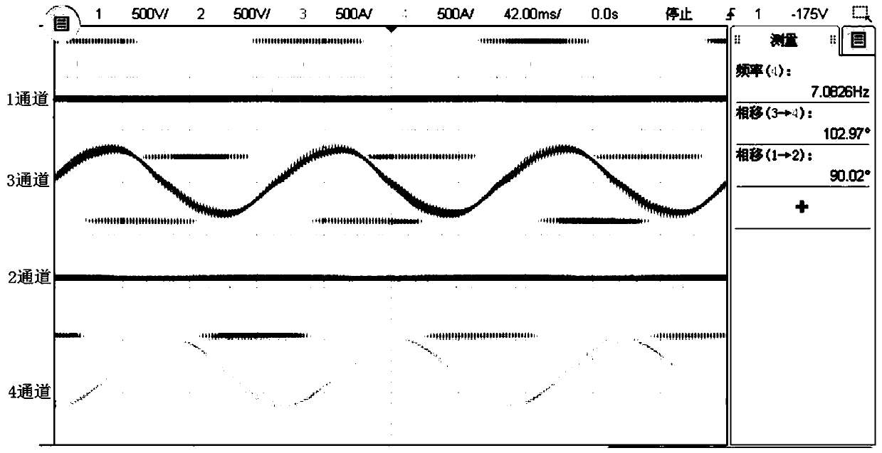
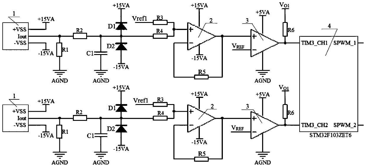

Image

  • Method and device for correcting the magnetic field direction of a slab electromagnetic stirrer
  • Method and device for correcting the magnetic field direction of a slab electromagnetic stirrer
  • Method and device for correcting the magnetic field direction of a slab electromagnetic stirrer

Examples


Embodiment Construction

[0053] The following will clearly and completely describe the technical solutions in the embodiments of the present application with reference to the accompanying drawings of the present application. Apparently, the described embodiments are only some of the embodiments of the present application, not all of them. Based on the embodiments in this application, all other embodiments obtained by persons of ordinary skill in the art without making creative efforts belong to the scope of protection of this application.

[0054] In the present invention, in order to achieve the best working effect of the slab electromagnetic stirrer, the phase angle difference between the phase currents flowing into the slab electromagnetic stirrer is detected in real time, and the phase angle of the current is corrected to the desired angle in real time.

[0055] The invention provides a method for correcting the magnetic field direction of a slab electromagnetic stirrer. The slab electromagnetic st...


PUM

PropertyMeasurementUnit
capacitanceaaaaaaaaaa

Abstract

The invention provides a method and a device for correcting the magnetic field direction of a slab electromagnetic stirrer. The correction method comprises the steps: collecting alternating current signals flowing through the K induction coils respectively; respectively converting the alternating current signals of the K induction coils into K alternating current voltage signals; respectively converting the K alternating current voltage signals into K alternating current voltage signals of which the bias voltage is V<REF>; comparing the K alternating current voltage signals with the bias voltage being VREF with a reference voltage V<REF> to obtain K square wave signals; capturing the moments when the rising edges of the K square wave signals are located, and calculating the phase difference between the square wave signals according to the moments when the rising edges of the K square wave signals are located; and adjusting the initial phase angle of the alternating current voltage in the K-phase alternating current power supply according to each phase difference so as to adjust the magnetic field direction of the slab electromagnetic stirrer, so that for any m value, the phase difference between the mth phase output voltage and the (m-1) th phase output voltage in the K-phase alternating current power supply is 2 (thetav<m>-thetav<m-1>)-delta theta<m, m-1>.

Description

technical field [0001] The invention relates to a method and a device for correcting the magnetic field direction of a slab electromagnetic stirrer. The invention relates to an electrical system of a slab electromagnetic stirrer, in particular to correction of the magnetic field direction of the slab electromagnetic stirrer in the secondary cooling zone and the crystallizer slab electromagnetic stirrer. Background technique [0002] The slab electromagnetic stirrer was initially applied to electromagnetic stirring in the secondary cooling zone, and then gradually developed to the application of electromagnetic stirring in the crystallizer. According to different metallurgical process requirements and different application locations on the continuous casting line. [0003] The slab electromagnetic stirrer is generally powered by two-phase (the phase angle difference between the two-phase voltages is 90°) or three-phase (the phase angle difference between the three-phase volt...

Claims


Application Information

Patent Timeline
Patent Type & Authority Applications(China)
IPC IPC(8): H02M5/18B01F13/08G01R25/00G01R29/18
CPCH02M5/18G01R25/00G01R29/18H02M1/0009B01F33/45
Inventor 汪亮刘勇任驰李爱武肖红王文宇袁鹏邹志强解苗陈民乐
Owner HUNAN ZHONGKE ELECTRIC
Learn More