
Artificial ankle joint talus component

A technology of talus and articular surface, applied in the field of talus elements of artificial ankle joint, can solve the problems of difficult to hit the correct position, exert impact force, improve and other problems, and achieve the effect of preventing dislocation and stably guiding

Pending Publication Date: 2020-07-03
科润泰克株式会社 +2
View PDF7 Cites 0 Cited by
  • Summary
  • Abstract
  • Description
  • Claims
  • Application Information

AI Technical Summary

Problems solved by technology

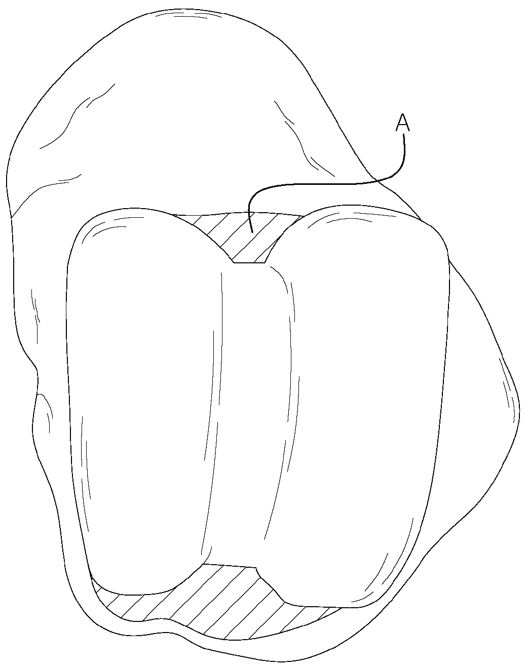
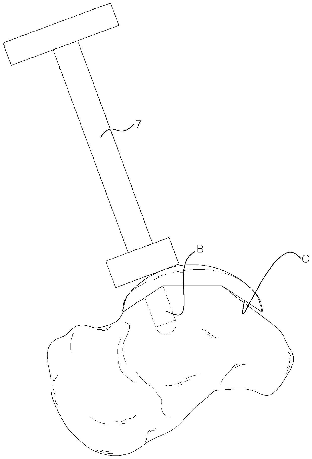
During surgery through a small incision site as described above, it is even difficult to hit exactly the right place when applying the impact force
Especially when the plug B is located in the front, it is necessary to apply force from the side when performing the impact, and in this case, the possibility of errors due to the inconvenient posture of the operator will further increase
[0018] As mentioned above, when the point of application of the force is deviated, the phenomenon that the rear part is lifted from the talus is caused, and this phenomenon becomes more serious when the plug B is located in the front C
In addition, while implants are usually made of solid metal, they are not rigid bodies, so even when force is applied correctly there is a small amount of deformation due to the force being concentrated in the front, which further leads to posterior Partial inability to securely seat on the talus
As mentioned above, because the plug B is located on the anterior side with a long distance from the posterior part, it will not be possible to ensure a firm combination of the talus and the implant when the contact on the posterior side is incomplete, and even after surgery because of the human body The load causes the rear part to sink and touch, still causing the problem of not being able to be seated exactly in the correct position
[0019] Since the above-mentioned phenomenon often occurs during the actual operation, it is necessary to use an image intensifier (image intensifier) ​​for real-time confirmation, which in turn leads to an increase in the risk of radiation exposure and infection for the operator

Method used


Image

  • Artificial ankle joint talus component
  • Artificial ankle joint talus component
  • Artificial ankle joint talus component

Examples


Embodiment Construction

[0076] Next, the talus element of the artificial ankle joint to which the present invention is applied will be described in detail with reference to the drawings. It should be noted that the same components in all the drawings are illustrated with the same symbols as much as possible. In addition, detailed descriptions of known functions and configurations that may make the gist of the present invention unclear will be omitted. Unless otherwise clearly defined, the meanings of all terms used in this specification are the same as the general meanings of the corresponding terms understood by those skilled in the technical field to which the present invention belongs, and should be the same as those used in this specification. In the event of a conflict in the meaning of a term, the definition used in this specification shall prevail.

[0077] Next, the talus element of the artificial ankle joint to which the present invention is applied will be described in detail with reference t...


PUM


Abstract

The present invention relates to an artificial ankle joint talus component and, more specifically, to an artificial ankle joint talus component comprising: a joint surface coming in contact with an insert; and a contact surface coming in contact with the bone, wherein the contact surface is formed in a shape complementary to the cross section of the talus, thereby repairing the entire cross section and thus distributing stress, and reducing side effects such as osteolysis or heterotopic ossification after the surgery.

Description

Technical field [0001] The present invention relates to an artificial ankle joint talus element, in particular to an articular surface that is connected to an insert and a contact surface that is connected to the bone. The contact surface is formed in a shape that complements the tangent surface of the talus, so that it can be aligned All cut surfaces are repaired and the stress is dispersed, and it can also reduce the postoperative osteolysis or heterotopic ossification and other side effects of the artificial ankle talus element. Background technique [0002] When the ankle joint cannot function normally due to various reasons such as degenerative arthritis of the ankle and post-traumatic arthritis, a replacement surgery using an artificial ankle joint will be performed. The artificial ankle replacement surgery that began in the 1970s showed many side effects in the early stage, and its clinical results were far from people's expectations. Moreover, because of the high complexi...

Claims


Application Information

Patent Timeline
Patent Type & Authority Applications(China)
IPC IPC(8): A61F2/42
CPCA61F2/42A61F2/4202A61F2002/30878A61F2002/4207A61F2002/30843A61F2002/30138A61F2002/3093
Inventor 李根培慎太珍
Owner 科润泰克株式会社
Learn More