Glass cleaning robot and cleaning method

A technology for cleaning robots and cleaning water, applied in cleaning machinery, machine parts, aircraft, etc., can solve the problems of high energy consumption, low precision of cleaning drones, and small scope of application

Pending Publication Date: 2020-07-07
BEIJING HUALANDE TECH CONSULTING SERVICE CO LTD
View PDF7 Cites 1 Cited by
  • Summary
  • Abstract
  • Description
  • Claims
  • Application Information

AI Technical Summary

Problems solved by technology

[0004] Therefore, the technical problem to be solved by the embodiments of the present invention is to overcome the defects of low precision, high energy consumption, and small scope of application of cleaning drones in the prior art, thereby providing a glass cleaning robot and cleaning method

Method used


Image

  • Glass cleaning robot and cleaning method
  • Glass cleaning robot and cleaning method
  • Glass cleaning robot and cleaning method

Examples


Embodiment 1

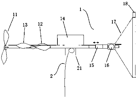
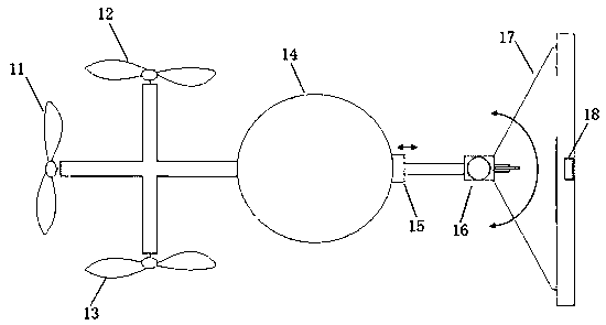
[0073] This embodiment provides a cleaning robot, such as figure 1 , figure 2 and Figure 6 As shown, it includes: UAV 1, tethered rope 2 and ground trolley 3; for example, UAV 1 is a quadrotor UAV or others.

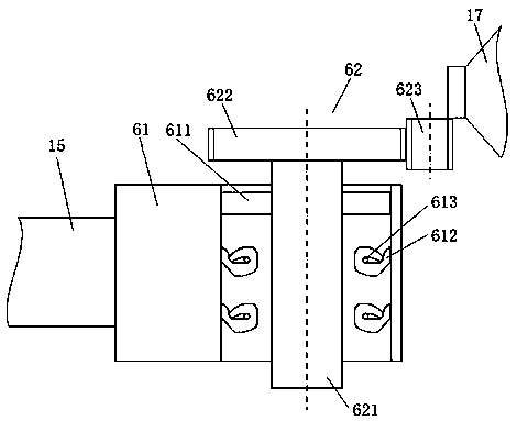
[0074] UAV 1 comprises cleaning reaction force regulating device, four-rotor mounting base 14, telescopic rod device 15, steering gear 16, cleaning device 17 and distance and angle detection device 18; Connection; the telescopic long rod device 15 is installed directly below the center of gravity of the four-rotor mounting base 14, and includes a telescopically adjustable long rod for driving the cleaning device 17 to move forward and backward with the telescopic adjustment of the long rod; the steering device 16 includes The fixed seat 61 and the rotating body 62, the fixed seat 61 is connected with one end of the telescopic rod device 15, the rotating body 62 is connected with the cleaning device 17, and is used to drive the cleaning device 17 to rotate left and ri...

Embodiment 2

[0085] Cleaning preparation: After the control parameters are input into the controller of the ground trolley, for example, the GPS / Beidou positioning module is used to control the ground trolley to travel to the predetermined position. At the same time as the UAV takes off, the mooring hoisting device on the ground trolley is controlled by the tension controller The hoisting reel releases the mooring rope with the take-off speed of the UAV; the UAV flies to the preset working height and feeds back to the ground trolley, and the ground trolley controls the cleaning water and cleaning fluid in the liquid storage device to be sent through the tethering rope. to the drone cleaning unit.

[0086] After completing the preparatory steps for cleaning, this embodiment provides a cleaning method that can be applied to the controller 32 to complete the cleaning. Such as Figure 7 As shown, the cleaning method includes the following steps:

[0087] S1. Obtain the angle between the end ...


PUM


Abstract

The invention discloses a glass cleaning robot and a cleaning method and belongs to the field of unmanned aerial vehicle control. The cleaning robot comprises an unmanned aerial vehicle, a mooring rope and a ground trolley; the unmanned aerial vehicle comprises a cleaning reaction force adjusting device, a telescopic long rod device, a steering device and the like; the telescopic long rod device comprises a telescopic adjustable long rod and is used for driving the cleaning device to move back and forth along with the telescopic adjustment of the long rod; the steering device comprises a fixing base and a rotating body and is used for driving the cleaning device to rotate leftwards and rightwards along with rotating adjustment of the rotating body; the cleaning reaction force adjusting device is connected with the other end of the telescopic long rod device and used for generating a pair of reaction forces acting on the unmanned aerial vehicle when the cleaning device sprays liquid; the mooring rope is used for conveying power supply power of the unmanned aerial vehicle, transmitting a control signal and conveying cleaning water and cleaning liquid for cleaning; the ground trolleyis used for generating the control signal and storing the cleaning liquid. The glass cleaning robot of the invention has the advantages of low power and wide application range.

Description

technical field [0001] The invention relates to the field of unmanned aerial vehicle control, in particular to a glass cleaning robot and a cleaning method. Background technique [0002] Most of the drones currently on the market are mainly used for drone flight, photography, inspection, plant spraying, etc., and, in the existing drone applications that can be used as operating platforms, the application Most of them are mainly hoisting, vertical throwing, vertical traction and other operations. One of the main features of these applications is that their working direction is perpendicular to the ground direction. That is, the propeller of the UAV is located directly above the entire operation platform. As long as the center of gravity of the UAV operation process does not shift too much, under the control of the flight control system, the entire operation process and operation stages are of great importance to the flight of the UAV. It won't have much of an impact. Howev...

Claims


Application Information

Patent Timeline
Patent Type & Authority Applications(China)
IPC IPC(8): A47L1/02A47L11/38A47L11/40E04G23/00B64C39/02B64D1/18
CPCA47L1/02A47L11/38A47L11/40A47L11/4002A47L11/4011A47L11/4052A47L11/4088E04G23/002B64C39/022B64D1/18A47L2201/04A47L2201/06B64U10/10B64U2101/00B64U2201/202
Inventor 连芷萱李奕成连一帆宋绍鑫
Owner BEIJING HUALANDE TECH CONSULTING SERVICE CO LTD
Why Eureka
Try Eureka