Rapid welding manipulator

A fast welding and manipulator technology, applied in the field of manipulators, can solve problems such as faults at the movable joints of welding manipulators

Inactive Publication Date: 2020-07-07
牟立兵
View PDF9 Cites 1 Cited by
  • Summary
  • Abstract
  • Description
  • Claims
  • Application Information

AI Technical Summary

Problems solved by technology

[0003] Since the welding manipulator will generate spattering sparks when welding the automobile steel plate, and the sparks will form metal particles after cooling. When the sparks fall into th

Method used


Image

  • Rapid welding manipulator
  • Rapid welding manipulator
  • Rapid welding manipulator

Examples


Embodiment 1

[0031] For example figure 1 -example Figure 7 Shown:

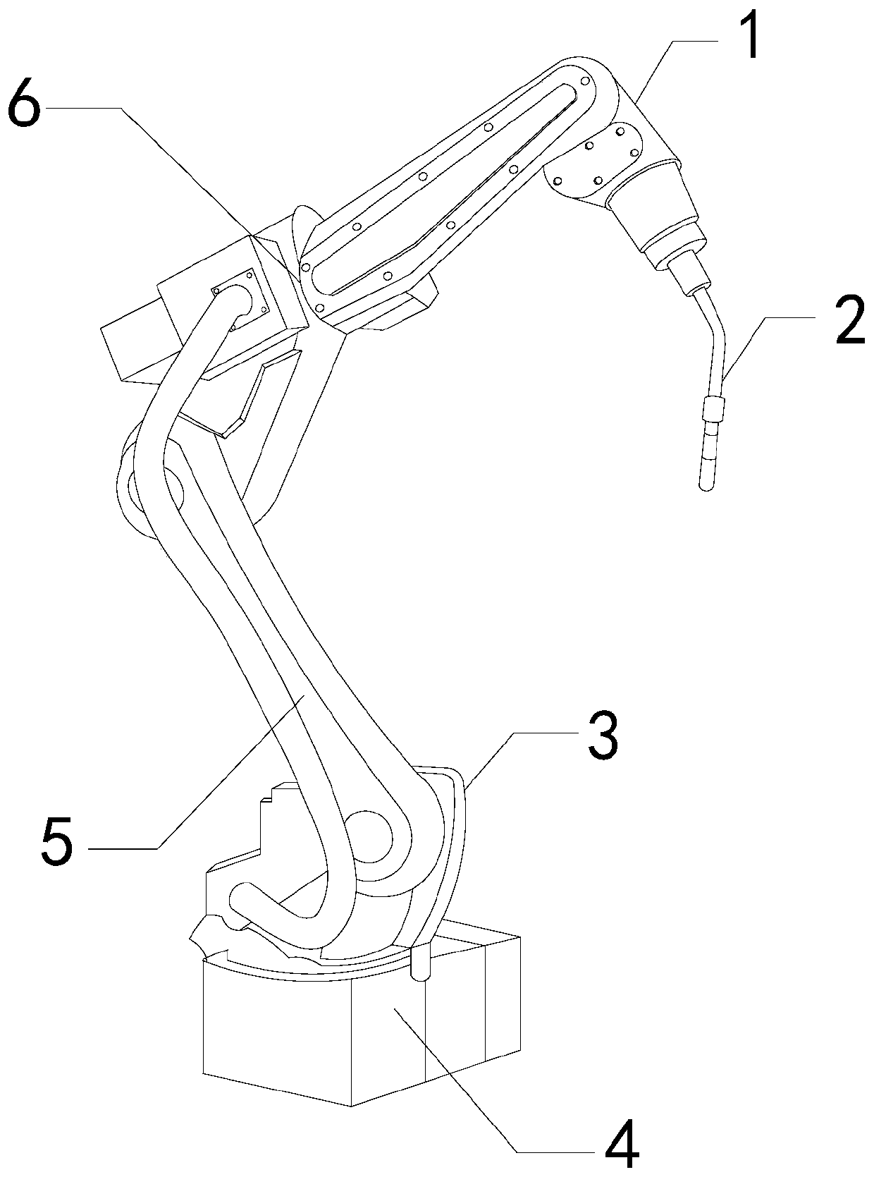
[0032] The invention provides a fast welding manipulator, the structure of which includes a manipulator 1, a welding torch 2, a steering support 3, a base 4, an engaging rod 5, and a movable rod 6. The welding torch 2 is embedded and connected to the manipulator 1, and the steering support 3 is movably engaged with the base 4, the base 4 is fixed at the lower end of the manipulator 1, the movable rod 6 is connected with the connecting column 5, and the connecting rod 5 is movably engaged with the steering support 3.

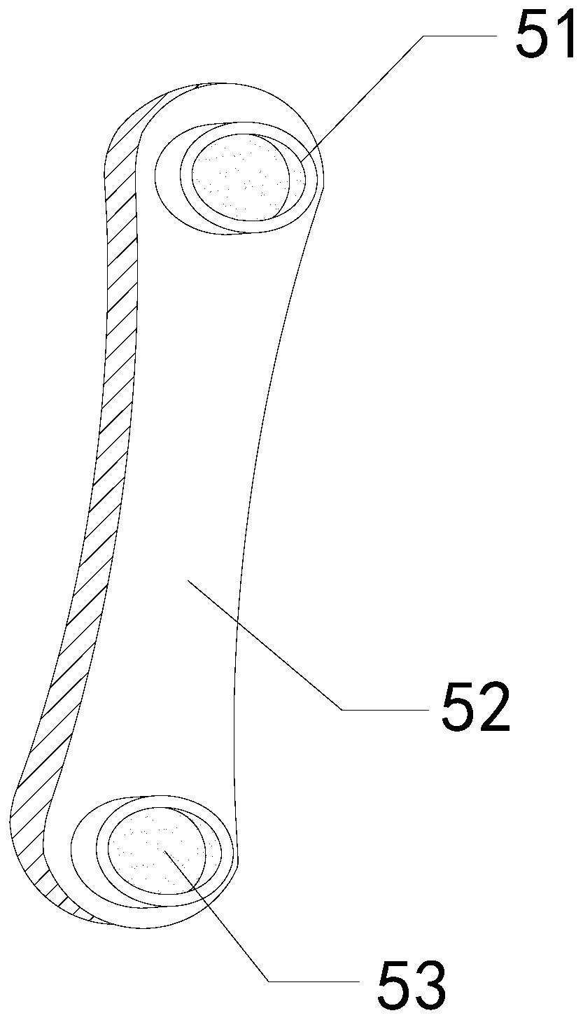
[0033] Wherein, the connecting rod 5 includes a shield 51, a fixed rod 52, and a connection port 53, the shield 51 is installed at an external position of the connection port 53, the connection port 53 is embedded and connected with the fixed rod 52, and the shield The cover 51 has a circular structure, which can better protect the connection port 53 .

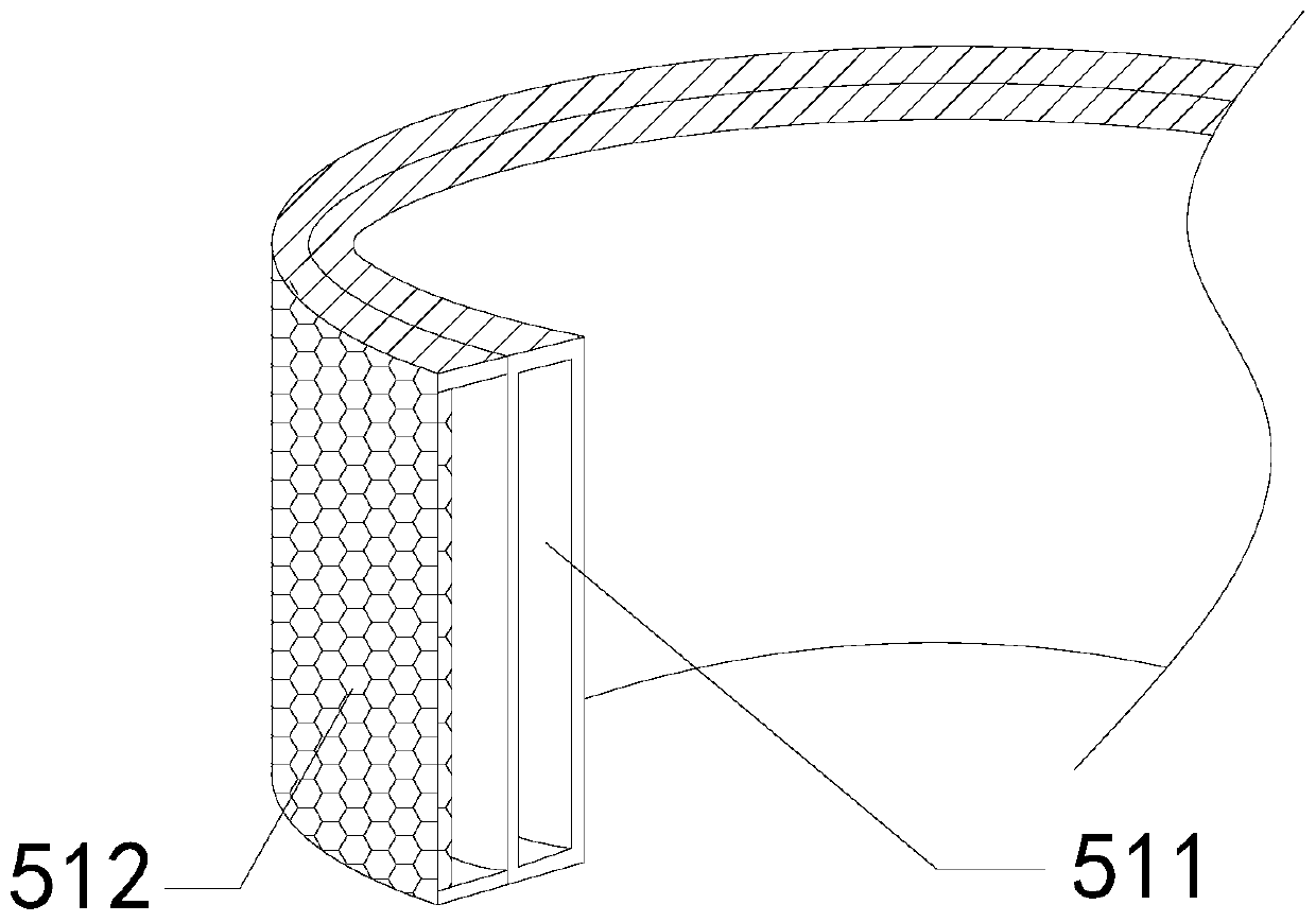
[0034] Wherein, the shield 51 includes a fixed inne...

Embodiment 2

[0042] For example Figure 8 -example Figure 10 Shown:

[0043] Wherein, the movable outer ring 512 includes a baffle c1, a clearing mechanism c2, and a through-hole plate c3, the baffle c1 is embedded and connected with the clearing mechanism c2, and the through-hole plate c3 is embedded and connected with the baffle c1. The perforated plate c3 has a porous structure, which can allow splashing sparks to enter from all angles, effectively improving the treatment effect on sparks.

[0044] Wherein, the cleaning mechanism c2 includes a brush head c21 and a fixed pipe c22, the brush head c21 is embedded and connected with the fixed pipe c22, and the fixed pipe c22 is installed at the rear end of the brush head c21, and the brush head c21 adopts a hardness The higher polyurethane sponge is beneficial for the brush head c21 to remove welding slag.

[0045] Wherein, the fixed pipe c22 includes a housing c221, a seepage pipe c222, and a liquid receiving chamber c223, the housing ...


PUM


Abstract

The invention discloses a rapid welding manipulator. The rapid welding manipulator structurally comprises a manipulator, a welding gun, a steering support, a base, a connecting rod and a movable rod,wherein the welding gun is fixedly connected with the manipulator in an embedded mode, the steering support is movably clamped to the base, the base is fixed to a lower end of the manipulator, the movable rod is connected with the connecting rod, and the connecting rod is movably clamped to the steering support; when the manipulator welds a metal product through the welding gun, splashed sparks can be effectively isolated through the protective cover on the connecting rod, and the situation that a movable joint of the manipulator is easily damaged by metal particles condensed after the sparkssplashed to the movable joint of the manipulator are cooled can be avoided; due to the fact that the area, whether welding slag can be attached, of a blocking face is limited, the welding slag attached to the blocking face can be removed through the matching of a fixed pipe and a brush head, and the situation that the collecting efficiency to the welding slag by the blocking face is reduced due toexcessive welding slag attached to the blocking face is avoided.

Description

technical field [0001] The invention relates to the field of manipulators, in particular to a fast welding manipulator. Background technique [0002] The welding manipulator is mainly used for welding metal products. It can weld metal products through the welding torch at the end, which greatly improves labor productivity. It is widely used in automobile production and other industries. Based on the above description, the inventor found that the present invention A kind of fast welding manipulator that has mainly has the following deficiencies, for example: [0003] Since the welding manipulator will generate spattering sparks when welding the automobile steel plate, and the sparks will form metal particles after cooling. When the sparks fall into the movable joints of the welding manipulator, it is easy to make the metal particles adhere to the movable joints. Accumulation can cause failure at the movable joints of the welding manipulator. Contents of the invention [0...

Claims


Application Information

Patent Timeline
IPC IPC(8): B23K37/02B23K37/00B23K37/08
CPCB23K37/006B23K37/02B23K37/08B23K2101/006B23K2103/04
Inventor 牟立兵
Owner 牟立兵
Why Eureka
Try Eureka