Spliced composite slab structure

A technology of laminated slabs and laminated layers, applied in the direction of structural elements, floor slabs, building components, etc., can solve the problems of unreasonable structural stress, low density, and inability to completely cover the interface.

Pending Publication Date: 2020-07-07
ELITE ARCHITECTURAL CO LTD
View PDF0 Cites 0 Cited by
  • Summary
  • Abstract
  • Description
  • Claims
  • Application Information

AI Technical Summary

Problems solved by technology

After the construction and installation of the prefabricated floor and the cast-in-place laminated concrete form a laminated slab (normal operating condition), a shear structure needs to be set at the interface between the prefabricated floor and the cast-in-place laminated layer of the laminated slab, while the existing The layout density of the truss reinforcement is not high, and the joint surface cannot be completely covered, and the structural force is unreasonable
And at the construction site, for the spliced ​​truss reinforcement laminated slabs, the connecting reinforcement between the slabs and the stress reinforcement of the cast-in-place laminated layer need to be manually bound to the truss reinforcement, which will cause a large workload on the construction site and reduce construction efficiency. high cost

Method used


Image

  • Spliced composite slab structure
  • Spliced composite slab structure
  • Spliced composite slab structure

Examples


Embodiment Construction

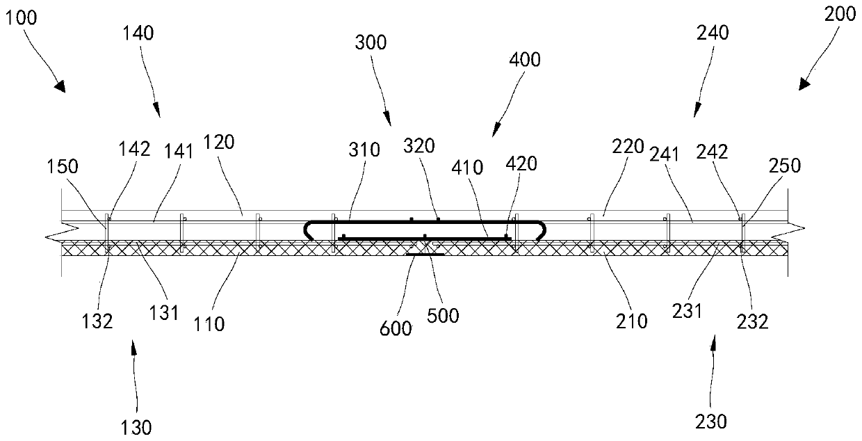
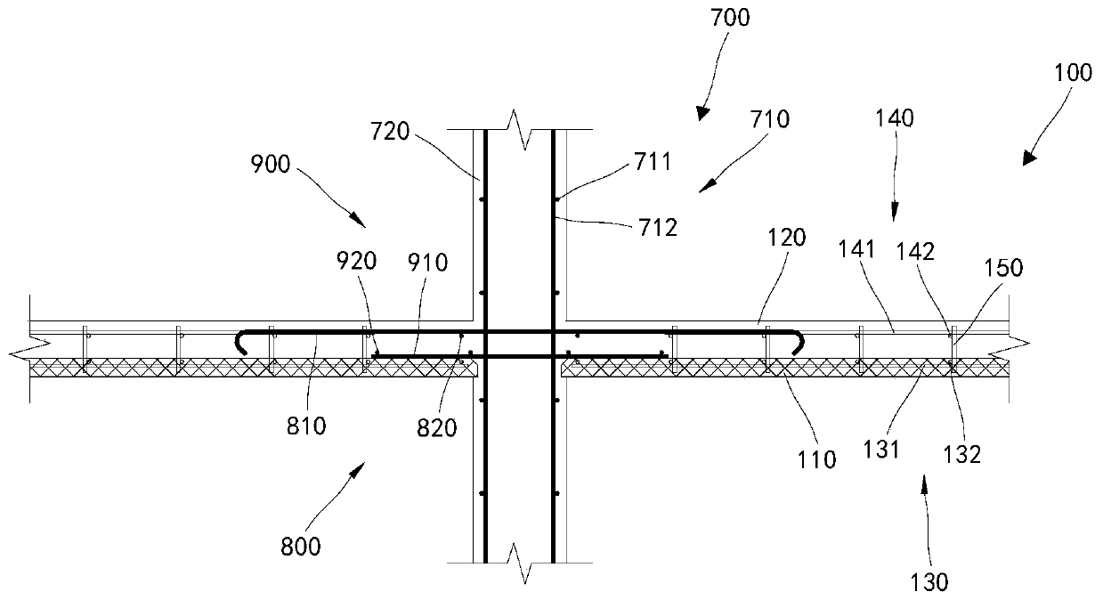
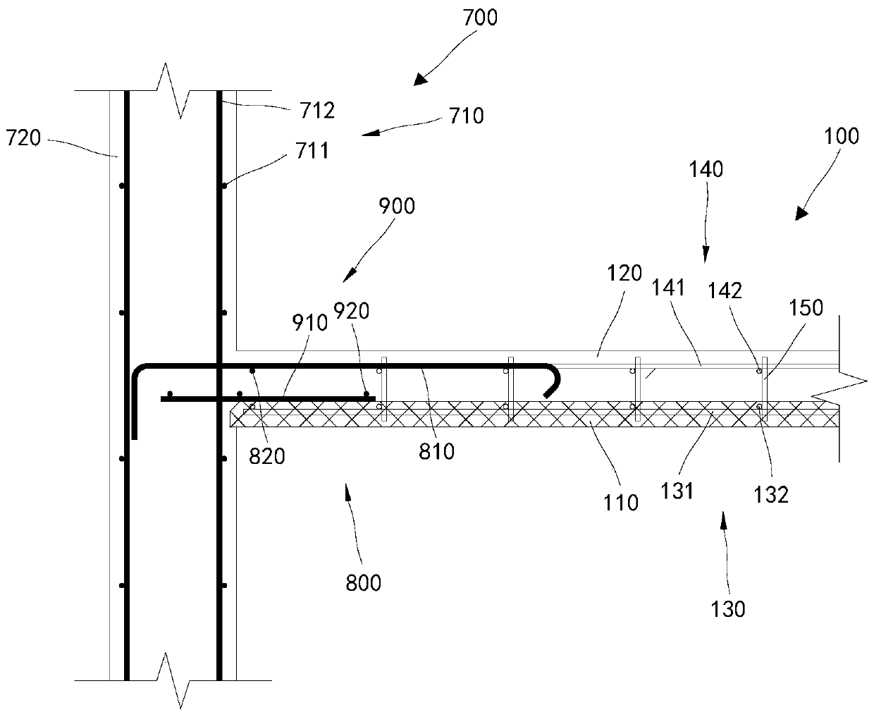
[0037] The specific implementation manners of the present invention will be further described in detail below in conjunction with the accompanying drawings and embodiments. The following examples are used to illustrate the present invention, but are not intended to limit the scope of the present invention.

[0038] In the description of the present invention, it should be noted that the terms "upper", "lower", "front", "rear", "left", "right", "vertical", "horizontal", "top", The orientation or positional relationship indicated by "bottom", "inner", "outer", etc. is based on the orientation or positional relationship shown in the drawings, and is only for the convenience of describing the present invention and simplifying the description, rather than indicating or implying the referred device or positional relationship. Elements must have certain orientations, be constructed and operate in certain orientations, and therefore should not be construed as limitations on the invent...


PUM


Abstract

The invention relates to the technical field of buildings, and discloses a spliced composite slab structure. The structure comprises a first composite slab and a second composite slab; the first composite slab comprises a first prefabricated slab, a first cast-in-place composite layer and a first welded steel bar frame; the second composite slab comprises a second prefabricated slab, a second cast-in-place composite layer and a second welded steel bar frame; a first stressed steel bar assembly and a first connecting steel bar net are arranged between the first composite slab and the second composite slab; the first prefabricated slab abuts against the second prefabricated slab; and the first cast-in-place composite layer and the second cast-in-place composite layer are integrated by pouring. According to the structure, the first welded steel bar frame and the second welded steel bar frame are of integral grid steel bar structures and play a role in welding fixing so that the thicknessof the first prefabricated slab and the second prefabricated slab can be reduced when being manufactured, the anti-shearing effect is evenly achieved, a large number of steel bars do not need to be bound on site, the workload on a construction site is greatly reduced, and the construction efficiency is improved.

Description

technical field [0001] The invention relates to the technical field of construction, in particular to a spliced ​​laminated plate structure. Background technique [0002] At present, the most commonly used floor form of prefabricated concrete structures in the construction industry is the truss reinforced concrete laminated slab, which is fixed on the support with steel bars, and finally concrete is poured on the support and one or more spliced ​​laminated slabs to be poured. [0003] The main function of the truss reinforcement used in the existing laminated slab is to increase the rigidity and bearing capacity of the prefabricated floor during demoulding and hoisting of the prefabricated floor components (short-term working conditions). After the construction and installation of the prefabricated floor and the cast-in-place laminated concrete form a laminated slab (normal operating condition), a shear structure needs to be set at the interface between the prefabricated flo...

Claims


Application Information

Patent Timeline
Patent Type & Authority Applications(China)
IPC IPC(8): E04B5/38E04C5/06
CPCE04B5/38E04C5/064
Inventor 张艾荣黎加纯李一品许文杰陈敬恒邓宝瑜杨小威
Owner ELITE ARCHITECTURAL CO LTD
Why Eureka
Try Eureka